|
| |
TM 5-4210-233-14&P-1
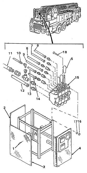
5-56. LADDER CONTROL VALVE
This task covers:
a.
Removal
c.
Follow-on Maintenance
b.
Installation
TOOLS REQUIRED:
EQUIPMENT CONDITION
Tool Kit, General Mechanics, Automotive
Ladder Bedded (see para 2-14.)
(Appendix B, Section III, Item 1)
Main Engine Shutdown (see para 2-12.)
APU Shutdown (see para 2-16.)
MATERIALS/PARTS REQUIRED
Batteries Disconnected (see para 4-114.)
Hydraulic Oil (Item 28, Appendix E)
Tags, Identification (Item 32, Appendix E)
a.
Removal.
(1) Be sure ladder is completely lowered and
resting on ladder supports on cab roof.
(2) With engine shutdown and emergency
hydraulic circuits deactivated, operate all
three ladder control levers in both
directions to relieve all hydraulic pressure
in ladder oil lines.
(3) Remove twelve screws (1) and remove
panels (2 and 3) and open door (4).
(4) Remove three knobs (5) from valve
handles by turning knob in counter-
clockwise direction.
(5) Tag and disconnect nine hoses (6 thru 14)
from ladder control valve (15).
(6) Remove three nuts (16), washers (1 7) and
bolts (18) and remove ladder control valve.
b.
Installation.
(1) Place ladder control valve (1 5) in position
and install three bolts (1 8) with washers (1
7) and nuts (1 6).
(2) Connect nine hoses (6 thru 14) to ladder
control valve (15).
(3) Install knobs (5) on handles and tighten in a
clockwise direction.
(4) Install panels (2 and 3) close door (4) and
secure with twelve screws (1).
(5) Check level of fluid in hydraulic tank and
add hydraulic oil (Item 28, Appendix E) as
required (see para 5-48).
5-341
|

