|
| |
TRUCK SERVICE MANUAL
TM 5-4210-230-14&P-1
STEERING GEAR
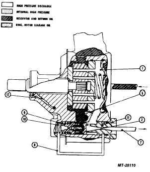
The high pressure discharge oil (7) is slightly lower in
pressure than the internal high pressure oil (1). The drop in
pressure occurs as oil flows through the flow control orifice
(2). This reduces the pressure at the bottom end of the pump
control valve (9) because the orifice (11) is connected by
passage (8) to (9) resulting in a pressure unbalance on the
valve. The flow control valve moves away from the discharge
fitting, but due to the force of the flow control spring (10) the
valve remains closed to the bypass hole (5). The oil pressure
does not build up high enough to cause the pressure relief
valve to actuate, because the oil pumped through the steering
gear is allowed to recirculate through the entire system.
Fig. 4 Slow Cornering
Fig. 4 Slow Cornering
MODERATE TO HIGH SPEED OPERATION (FIG. 5)
When operating at moderate to high speed, it is
desirable to limit the temperature rise of the oil. This is done
by flow controlling. The control valve in the steering gear is
an open center rotary valve. When this valve is in the straight
ahead position, oil flows from the pump through the open
center valve and back to the pump reservoir without traveling
through the power steering gear. When this flow exceeds the
predetermined system requirements, oil is bypassed within
the pump. This is accomplished by the pressure drop which
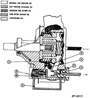
occurs across the flow control orifice (2). The pressure is
reduced at the bottom of the flow control valve (9) because
the orifice (11) is connected by (8) to the bottom of valve (9).
Fig. 5 Flow Controlling
The pressure unbalance of the valve is sufficient to
overcome the force of the spring (10), allowing the valve to
open the bypass hole (5), and diverting oil into the intake
chamber (6). Supercharging of the intake chamber occurs
under these conditions. Oil at high velocity discharging past
the valve into the intake chamber picks up make-up oil at hole
(4) from the reservoir on the jet pump principle. By reduction
of velocity, velocity energy is converted into supercharge
pressure in cavity (6). During this straight ahead driving
condition, the discharge pressure should not exceed 690
kilopascals (100 PSI).
CORNERING AGAINST WHEEL STOPS (FIG. 6)
When the steering gear control valve is actuated in
either direction to the point of cut-off, the flow of oil from the
pump is blocked. This condition occurs when the front wheels
meet the wheel stop, or when the wheel movement is
otherwise blocked by a curb or deep sand or mud. The pump
is equipped with a pressure relief valve. The relief valve is
contained inside the flow control plunger (13). When the
pressure exceeds a predetermined pressure, (greater than
maximum system requirements) the pressure relief ball (14)
opens, allowing a small amount of oil to flow into the bypass
hole (5). This flow of oil passing through the pressure relief
orifice (11) causes a pressure drop and resulting lower
pressure on the bottom end of the control valve (9).
CTS-2296R Chapter 1, Page 7
PRINTED IN UNITED STATES OF AMERICA
|


