|
| |
TRUCK SERVICE MANUAl
TM5-4210-230-14&P-1
STEERING
DESCRIPTION
The housing and internal parts of the pump are
inside the reservoir so that the pump parts operate submerged
in oil. The reservoir is sealed against the pump housing,
leaving the housing face and the shaft hub exposed. The
reservoir has a filler neck fitted with a cap. On the 125 series
pump, a shaft bushing and seal are pressed into the housing
from the front. The drive shaft is inserted through this seal
and bushing. On the 235 series pump, the shaft is supported
in the front with a ball bearing and in the back with a needle
bearing. The drive shaft seal is pressed into the housing and
located behind the ball bearing. A large hole in the rear of the
housing contains the functional parts; namely ring, rotor,
vanes and plates. A smaller hole contains the control valve
assembly and spring.
The thrust plate (Figs. 1 & 2) is located on the inner
face of the housing by two dowel pins. This plate has four
central blind cavities for undervane oil pressure. The two
outer blind cavities direct discharge oil through the two cross-
over holes in the pump ring (Fig. 3), through the pressure
place and into cavity 1 (Fig. 4). The two outside indentations
in the thrust plate are for intake of the oil from the suction part
of the pump.
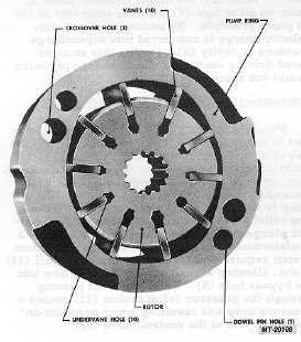
The pump ring (Fig. 3) is a plate having the mating
surfaces ground flat and parallel. The center hole is a two-
lobed cam in which the rotor and vanes operate. The ring is
placed next to the thrust plate and located with the same
dowel pins.
Fig. 3 Pump Ring and Rotor
The pressure plate is fitted against the ring and
located with the same two dowel pins. This plate has six
through ports. The four central through ports connect from
cavity 1 (Fig. 4) to supply undervane oil pressure. The two
outer ports pass oil under discharge pressure to cavity 1. The
two indentations are for oil intake from the suction part of the
pump, cavity 6 (Fig. 5) into the rotor.
The reservoir is for oil storage. It receives and
directs the return oil back to the make-up passage of the
pump.
The drive shaft is fitted with a pulley and is belt
driven from the crankshaft. The rotor is loosely splined to the
drive shaft and secured with a retaining ring. It is located
centrally within the ring and between the thrust and pressure
plates. The ten vanes are mounted in radial slots in the rotor
(Fig. 3).
OPERATION
The mode of operation of the power steering pump is
based upon the demand of the power steering system. The
various major modes of operation are: slow cornering,
moderate to high speed straight ahead driving, and cornering
against the wheel stop. The pump is designed to recognize
these conditions as required by the steering gear valve and
compensate for them internally.
As the drive shaft turns the rotor, the vane tips follow
the inner cam surface of the pump ring, moving outward and
inward twice during each revolution. This results in a
complete pumping cycle every 180 degrees of rotation (Fig.
3). Oil is moved in the spaces between the vanes. As the
vane tips move outward, oil is sucked into the inter-vane
spaces through four suction ports in the pressure and thrust
plates. The pressure of the oil is raised, and the oil is
discharged from the pump ring, as the vane tips move inward.
High pressure oil discharges into cavity 1, (Fig. 4), through
two open ports in the pressure plate, and through two blind
ports in the thrust plate, which are connected to cavity 1 by
the cross-over holes in the ring. A portion of this oil is
circulated through the central port system in the pressure
plate, forcing the vanes to follow the cam surface of the ring.
The ring-rotor leakage oil 12 (Fig. 4) is used for bushing
lubrication and then bled to the reservoir.
SLOW CORNERING (FIG. 4)
During slow cornering maneuvers, the oil pressure
required will usually not exceed 2760 kilopascals (400 PSI)
RPM of the pump is not high enough to require internal
bypassing of oil; therefore, the pump bypass port to (5)
remains closed.
CTS-2296R Chapter 1, Page 3
PRINTED IN UNITED STATES OF AMERICA
|