|
| |
TRUCK SERVICE MANUAL
TM 5-4210-230-14&P-1
STEERING GEAR
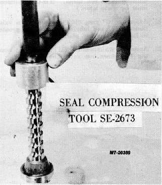
Fig. 23
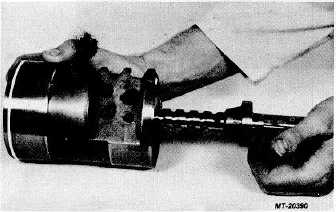
Fig. 24
8.
Assemble clip (44) or seal (47) and cap (48) onto
rack piston (31).
9.
Assemble two lockwashers (45), if applicable.
10.
Assemble two screws (46) or (49). Torque screws
(46) to 15-20 Nm (11-15 ft.lbs.), torque screws (49)
to 20-26 Nm (15-19 ft. lbs.). Screws (49) have a
locking feature and lockwashers (45) are not
required.
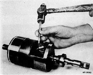
11.
Bend tabs on two lockwashers (45) up against flat on
screws (46) (Fig. 26).
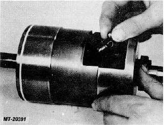
Fig. 25
Fig. 26
12.
Apply a generous amount of clean grease to seal ring
(29) area of rack piston (31) and assemble rack
piston and worm shaft assembly into housing
(20)(Fig. 27).
13.
Assemble sealing nut (38) onto adjusting screw (39)
with sealing side to be against end cover (37)(Fig.
28).
14.
Assemble adjusting screw (39) into end cover (37) a
few turns. (Final adjustment must be made later.)
15.
Assemble sealing nut (3) onto adjusting screw (40)
with sealing side to be against end cover (37).
16.
Assemble adjusting screw (40) into end cover (37) a
few turns. (Final adjustment must be made later.)
CTS-2717 Page 9
PRINTED IN UNITED STATES OF AMERICA
|