|
| |
TRUCK SERVICE MANUAL
TM 5-4210-230-14&P-1
STEERING GEAR
to an internal combustion engine. The housing
should be replaced if the steering gear is tested
thoroughly and it can definitely be determined that
cylinder bore scoring is responsible for excessive
internal leakage.
39.
If bearing (21) and retaining ring (22) require
replacement they must be pressed out of housing
(20). Care must be taken to maintain a good square
relationship between housing and press base, to
avoid damaging bearing bore. If bearing is "cocked"
while being pressed out, it may burnish housing bore,
causing it to be oversize and require housing
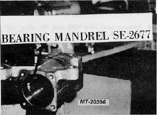
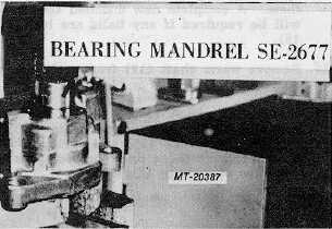
replacement. Use bearing mandrel SE-2677 to press
bearing out (Fig. 20).
Fig. 20
REASSEMBLY
IMPORTANT
All gaskets, seals and seal rings should be replaced each time
steering gear assembly is fully disassembled. If
steering gear is partially disassembled all gaskets,
seals and seal rings in area effected should be
replaced.
1.
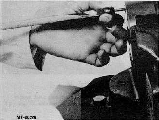
Press new bearing (21) into housing (20) using
bearing assembly mandrel SE-2677. Care must be
taken during this procedure to make sure that
housing is square with press base and that bearing is
not in a "cocked" position. Apply a generous amount
of clean wheel bearing grease to bearing race to
retain bearing rolls; assemble forty four bearing rolls,
grease must retain rolls (Fig. 21).
2.
Assemble "O" ring (30) and seal ring (29) onto rack
piston (31).
Fig. 21
3.
Assemble spring (36), rod (35), poppets (34), poppet
seals (33) and retaining ring (32) into rack piston
(31). Torque poppet seats to 27-34 Nm (20-25
ft.lbs.)(Fig. 22).
Fig. 22
4.
Assemble "O" ring (18) and seal ring (19) onto worm
shaft (17), use installation and compression tools
SE-2673 and SE-2674 to assemble these ports (Fig.
23).
5.
Grease seal ring (19) area and assemble worm shaft
(17) into rack piston (31)(Fig. 24).
6.
Assemble ball return guides (43) into rack piston
(31).
7.
Assemble balls (42) into ball return guides (43) and
rack piston (31); drop balls thru the hole provided in
the ball return guides. Rotate the worm shaft (17) as
balls are being assembled to pull balls down into
groove, assemble twenty-seven balls. Make sure ball
return guides stay down in place in rack piston while
assembling balls (Fig. 25).
CTS-2717 Page 8
PRINTED IN UNITED STATES OF AMERICA
|