|
| |
TRUCK SERVICE MANUAL
TM 5-4210-230-14&P-1
STEERING GEAR
Fig. 27
Fig. 28
17. Assemble "O" ring (10) into groove on end cover (37) and
lubricate with clean grease to hold "O" ring in place.
18. Assemble end cover (37) onto housing (20) with
four bolts (41). Torque bolts to 142-156 Nm (105-
115 ft.lbs.).
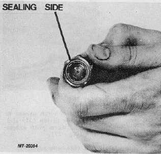
19. Assemble sealing nut (3) onto adjusting screw (2) with
sealing side to be against valve housing (9).
20. Assemble adjusting screw (2) into valve housing (9) a few
turns. (Final adjustment must be made later.)
21. Assemble "O" ring (10) into groove on valve housing (9)
and lubricate with clean grease to hold "O" ring in
place.
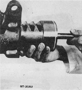
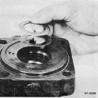
22. Assemble thrustwasher (11) and thrust bearing (12) down
into valve housing (9)(Fig. 29).
Fig. 29
Fig. 30
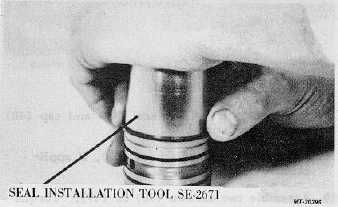
23.
Assemble "O" rings (14) and seal rings (13) onto
valve sleeve (15), use installation and compression
tools SE-2671 and SE-2672 (Figs. 30 and 31).
CTS-2717 Page 10
PRINTED IN UNITED STATES OF AMERICA
|