|
| |
TRUCK SERVICE MANUAL
TM 5-4210-230-14&P-1
STEERING GEAR
special care must be exercised to not lose them. A
complete new matched set of balls will be required if
any balls are lost (Fig. 15),.
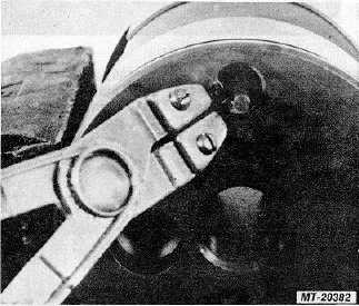
33.
Remove worm shaft (17) from rack piston (31).
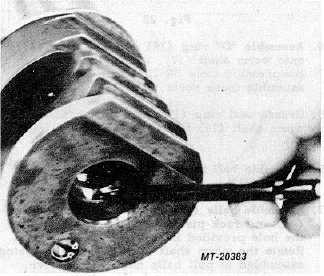
34.
Clamp rack piston (31) in a vise to remove retaining
rings (32), poppet seats (33), poppets (34), rods (35)
and spring (36). Do not remove these parts unless
there is evidence of damage (Fig. 16).
Fig. 16
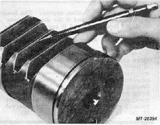
35.
Inspect rack piston (31) teeth and worm groove for
excessive wear marks (Figs. 17 and 18).
Fig. 17
Fig. 18
36.
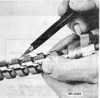
Remove seal ring (29) and "O" ring (30) from rack
piston (31). 37. Inspect worm shaft (17) helical
groove for brinelling (Fig. 19). If this condition is
visible the rack piston (31), valve sleeve (15) and
worm shaft must be replaced. Remove seal ring (19)
and "O" ring (18) from worm shaft.
Fig. 19
38.
Inspect housing (20) for abnormal wear, scoring or
damage. The housing should not be replaced simply
because the cylinder bore may exhibit considerable
scoring, this scoring should not be rated in any
manner relative to the type scoring which is critical
CTS-2717 Page 7
PRINTED IN UNITED STATES OF AMERICA
|