|
| |
TRUCK SERVICE MANUAL
TM 5-4210-230-14&P-1
STEERING GEAR
Fig. 12
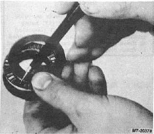
25. Loosen sealing nut (3) and adjusting screw (2) in
valve housing (9) approximately two turns.
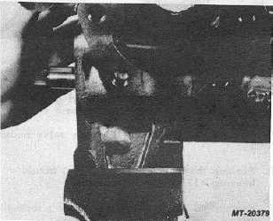
26. Remove rack piston (31) and worm shaft (17)
assembly from housing (20) (Fig. 13).
Fig. 13
27. Lay rack piston (31) and worm shaft (17)
assembly on a clean rag to keep from rolling and
to catch balls (42) as they come out. Bend locking
tabs down on lockwashers (45), if applicable,
some models of steering gears will not have
lockwashers.
28. Remove two screws (46) or (49), if applicable.
29. Remove clip (44) or cap (48), if applicable.
30. Remove seal (47) from cap (48), if applicable.
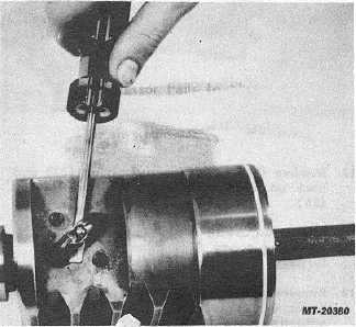
31. Remove ball return guides (43) and balls (42)
from rack piston (31). Ball return guides are
closely fitted into rack piston and may have to be
removed by carefully inserting a screwdriver
between rack piston and ball return guides' (Fig.
14).
Fig. . 14
Fig. 15
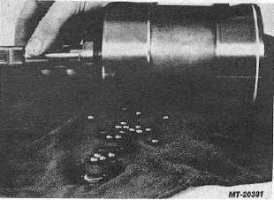
32. To remove balls, turn rack piston over so balls
can roll out as worm shaft is rotated in each
direction by small amounts. Assembly contains a
set of twenty-seven matched balls,
CTS-2717 Page 6
PRINTED IN UNITED STATES OF AMERICA
|