|
| |
TRUCK SERVICE MANUAL
TM 5-4210-230-14&P-1
STEERING GEAR
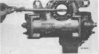
11. Remove seal (27) from trunnion cover (26) with a
screwdriver and remove four screws (28) from
trunnion cover and remove trunnion cover (Fig.
9).
Fig. 9
12. Remove seal (25), two-piece seal (23) and back-
up washer (24) from trunnion cover (26).
13. Loosen adjusting screw sealing nut (38) and
adjusting screw (39) approximately two turns with
a screwdriver and socket.
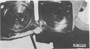
14. Remove four bolts (41) and remove end cover
(37)(Fig. 10). Loosen nut (3) and adjusting screw
(40) approximately two turns.
Fig. 10
15. Remove "O" ring (10) from end cover (37).
16. Remove relief valve (9A) from valve housing (9).
Remove "O" rings (9B) and (9D) and seal ring
(9C) from relief valve.
17.
Remove four bolts (1) from valve housing (9) and
remove valve housing.
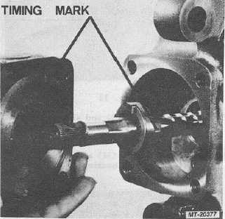
IMPORTANT
Proper valve function depends on valve sleeve
(15) and wormshaft (17) being reassembled in
their original assembled position. Timing marks
have been added to these parts so they can be
reassembled in their original position (Fig. 11).
Fig. 11
18. Do not remove drive ring (16) from worm shaft
(17) or attempt to unbend tangs which hold drive
ring in place on worm shaft.
19. Remove valve sleeve (15) from valve housing (9).
20. Remove thrust washers (11) and thrust bearing
(12) from valve housing (9).
21. Remove "O" ring (10) from valve housing (9).
22. Remove seal (4), retaining ring (5), back-up
washer (6), slipper (7) and "O" ring (8) from valve
housing (9).
23. Inspect thrust bearing (12) and thrust washers (11)
for wear marks or brinelling, replace if damaged
(Fig. 12).
24. Remove seal rings (13) and "O" rings (14) from
valve sleeve (15).
CTS-2717 Page 5
PRINTED IN UNITED STATES OF AMERICA
|