|
| |
TRUCK SERVICE MANUAL
TM 5-4210-230-14&P-1
STEERING GEAR
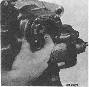
When sector shaft is being removed stop and
apply a generous amount of clean wheel bearing grease
to retain rolls in housing bearing (21)(Fig. 5).
Fig. 5
5.
Check to make sure all bearing (21) rolls are in
place after sector shaft (50) is removed.
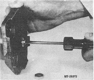
6.
Remove sector shaft adjusting screw nut (59).
7.
Screw sector shaft adjusting screw (51) thru side
cover (58) with a screwdriver and remove shaft
(50)(Fig. 6).
Fig. 6
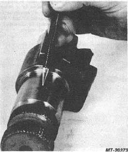
8.
Inspect sector shaft (50) bearing areas and tooth
surfaces for wear marks, pitting or brinelling. If
any of these conditions exist, replace sectorshaft
(Fig. 7).
Fig. 7
9.
Remove retaining ring (52), two-piece sea] (54),
(plastic) back-up washer (55) and (steel) back-up
washer (56) from side cover (58).
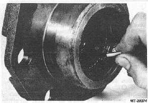
10. Remove bearing rolls from side cover (58),
inspect for wear marks; replace bearing if
required. Bearing and bearing rolls cannot be
replaced without replacing side cover (Fig. 8).
Fig. 8
CTS-2717 Page 4
PRINTED IN UNITED STATES OF AMERICA
|