|
| |
TRUCK SERVICE MANUAL
TM 5-4210-230-14&P-1
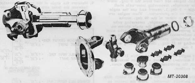
PROPELLER SHAFT
INSTALLATION
Fig. 42
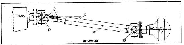
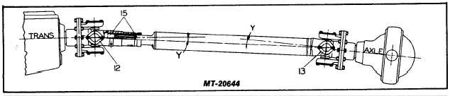
UNIVERSAL JOINT PHASING (See Fig. 37)
When u-joints or yokes are assembled to their shafts
in the same plane, they are in phase. When they are
assembled to the shaft in different planes, they are out of
phase. To obtain vibration free operation, check the following.
1.
Yokes or flanges between the main and auxiliary
transmission must be "In Phase"
2.
In the case of a two-piece driveshaft assembly,
between the transmission (Main or
Auxiliary) and the forward rear axle, the joints on this
shaft should be assembled "In Phase", unless
otherwise specified by the manufacturer of the
vehicle.
3.
The inter-axle driveshaft yokes must be "In Phase".
4.
If a vehicle has driveshafts that do not have
intersecting angles but parallel angles throughout the
drive line system, the yokes or flanges must be held
parallel to within 1 deg. of each other.
CTS-2730 Page 21
PRINTED IN UNITED STATES OF AMERICA
|