|
| |
TRUCK SERVICE MANUAL
TM 5-4210-230-14&P-1
PROPELLER SHAFT
INSTALLATION
INSTALLING DRIVESHAFT
Drive Shaft Assembly Place in a pair of centers and
check the shaft for run-out if not previously done during
assembly. The run-out on the tube should not be more than
.38 mm (.015") indicator reading, and on the neck of the slip
stub shaft the run-out should not be more than .12 mm (.005")
indicator reading. Mark the high and low points on the shaft
with chalk and straighten if necessary. Install with the slip
joint nearest the source of power. Tighten the flange bolts
evenly after the nuts and NEW lockwashers are in place.
CHECKING DRIVESHAFT ANGLES
The procedure to check driveshaft angles for proper
universal joint operating angles follows:
1.
Remember to check driveshaft angles both with the
tractor fifth wheel unloaded, and loaded with a trailer.
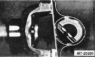
2.
To determine driveshaft angles, a spirit level
protractor is required (Fig. 43). When angles are
read from the 0 deg. mark (for example, measuring
inter-axle shaft angle 5 deg.), record and use the
angle shown on the protractor. When angles are
read from either of the 90 deg. marks (vertically) for
example, measuring yoke angles, do not record the
angle shown on the protractor since the 90 deg.
marks must be understood to be the same as 0 deg.
on the horizontal plane. Thus, if a vertical reading is
85 deg., the angle being measured is 5 deg.
3.
All angles should be read within 1/4 deg. (15
minutes) and they should be measured with the
protractor held plumb on a clean, flat surface.
4.
Inflate all tires to the pressure at which they are
normally operated. Park the tractor on a surface
which is as nearly level as possible both from front-
to-rear and from side to-side.
5.
The tractor must be in its normal operating position.
Do not attempt to level the truck by jacking up the
front or rear axles to obtain a level condition.
6. Check and record the angle on the engine and main
transmission. This reading can be taken at the rear
of the main transmission on the output yoke or
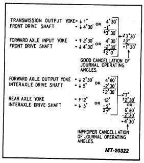
flange. Record this reading on a sketch similar to
Fig. 44 (Example on Fig. 45, -1 deg. down).
Fig. 43
7.
Move protractor to the 0 deg. reading and check
driveshaft angle between transmission and forward
axle (Example 4 deg. 30 sec. down).
8.
Check front axle input yoke angle with protractor
(Example angle up 2 deg. 30 sec.), also check front
axle output yoke (Example angle down 2 deg. 20
sec.).
9.
Measure the angle of the tandem driveshaft between
the front axle and first rear axle (Example 5 deg.
down).
10.
Measure the rear axle input yoke angle (Example 12
deg. up).
Fig. 44
CTS-2730 Page 22
PRINTED IN UNITED STATES OF AMERICA
|