|
| |
TRUCK SERVICE MANUAL
TM 5-4210-230-14&P-1
PROPELLER SHAFT
INSTALLATION
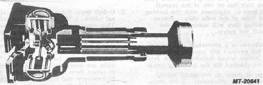
Lubricate the splines thoroughly (refer to page 9) and
assemble on the shaft. BE SURE that the arrows or marks on
the shaft and slip joint are in line, since the sleeve yoke lugs
must be in the same plane as the stud ball yoke lugs to
prevent excessive vibration (Fig. 37).
The cork washer should be replaced is necessary before
assembling with the dust cap and steel washer on the sleeve
yoke.
INSTALLING PROPELLER SHAFT
1.
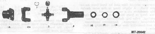
Propeller Shaft Assembly Place in a pair of centers
and check the shaft for run-out if not previously done
during assembly. The run-out on the tube should not
be more than .38 mm (.015") indicator reading, and
on the neck of the slip stub shaft the run-out should
not be more than .12 mm (.005") indicator reading.
Mark the high and low points on the shaft with chalk
and straighten if necessary. Install with the slip joint
nearest the source of power. Tighten the flange bolts
evenly after the nuts and NEW lockwashers are in
place.
Fig. 38
Fig. 39
TWO-JOINT PROPELLER SHAFT
It is of primary importance that universal joints of
sufficient capacity be used. When assembling the slip joint on
the shaft, care must be taken to place the sleeve yoke lugs
(12) in the same plane as the shaft yoke lugs (13). Arrows will
be found stamped on the sleeve and shaft for this purpose.
Install transmission so that the transmission main
shaft and axle pinion shaft are parallel or nearly so, in order to
keep the angles (X) on both joints as nearly equal as possible.
See Fig. 40. If this method results in angles (X) of more than
12 deg., use the method shown in Fig. 41, where the axle
pinion shaft is tilted upward to enable the centerlines to
intersect at a point midway between the joint centers, thus
giving equal angles (Y).
CTS-2730 Page 20
PRINTED IN UNITED STATES OF AMERICA
|