|
| |
TRUCK SERVICE MANUAL
TM 5-4210-230-14&P-1
PROPELLER SHAFT
INSTALLATION
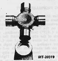
Fig. 36
JOURNAL CAPS WITH LOCK FLATS (Fig. 36)-
When installing new journal kit caps into yoke ear holes, the
lock flat on two of the journal caps must be kept in alignment
with the locking flats near the front of the yoke ears. Proper
location of locking flats will assure that the journal cap will not
rotate.
The installation of a driveshaft into the vehicle does
not present any unusual mechanical difficulties. Before actual
installation, the driveshaft should be checked for the following
items:
1.
No damage or dents on driveshaft tubing which could
cause unbalance. If the dents are severe enough
they can weaken the tube and a failure might occur
under torque load.
2.
Splines should slide freely with slight drag from
spline seal.
3.
Bearings should flex and be free from excessive bind.
A slight drag is the most desirable condition on a
new universal joint. This drag is from the bearing
seals. When rotating, yoke lug deflections cause
some additional clearance. Excessive looseness is
not desirable due to the resulting unbalance.
4.
Mounting flanges and pilots should be free from
burrs, paint and foreign substances which would not
allow proper seating at assembly.
The driveshaft is mounted using flange bolts, bearing
capscrews, or "U" bolts depending upon the size and
construction. These bolts must carry high torque loads and
should be of quality material and properly torqued. The
following reviews requirements on these bolts:
1.
Flange Bolts: Flange bolts should be alloy steel
equivalent to SAE Grade 8, high strength bolts.
These bolts used with spring lockwashers and nuts
provide the capacity required. The nuts should be
torqued to the following specifications:
N.m
Ft. Lbs.
5/16"-24 Thread
29.8-32.5
22-24
3/8"-24 Thread
54.2-59.6
40-44
7/16"-20 Thread
85.4-94.9
63-70
1/2"-20 Thread
132.9-146.4
98-108
IMPORTANT
In cap and bolt construction joints (Fig. 7), be
sure to torque the capscrews to 135.6 N.m
(100 ft.lbs.). These joints are usually in the
inter-axle assemblies.
2.
U-Bolt Style. Yokes: On smaller size universal joints,
a "U" bolt style end yoke is used. This construction
permits easier assembly where the smaller size
bearings allow its use. The bearing race is seated in
a half round hole and under locating ears. Be sure
that mounting faces are cleaned of rust, paint and
other foreign material. The "U" bolts are assembled
over the bearing races to retain them in the end
yokes. Spring lockwashers and nuts should be used
with these "U" bolts at assembly. The following
torque loads are suggested for use with these parts:
N.m
Ft. Lbs.
5/16"-24 Thread
18.9-23.0
14-17
3/8"-24 Thread
27.1-32.5
20-24
7/16"-20 Thread
43.3-50.1
32-37
These torque loads are somewhat lighter than
normally used with these thread sizes, however, the lower
torques are required to prevent bearing race distortion.
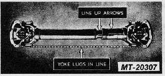
ASSEMBLING SLIP JOINT ON SHAFT
Fig. 37
CTS-2730 Page 19
PRINTED IN UNITED STATES OF AMERICA
|