|
| |
TRUCK SERVICE MANUAL
TM 5-4210-230-14&P-1
PROPELLER SHAFT
REBUILDING DRIVESHAFTS
BALANCING
The rebuilding of a driveshaft assembly usually
consists of replacing worn journal cross and bearings with a
new kit. These kits replace the part of a driveshaft most
subject to wear in operation. The slight off-center condition
present in the journal cross assemblies makes it desirable to
balance the assembly after installing new journal and bearing
kits.
Generally, unbalance resulting after installation of a
journal and bearing kit is equivalent to the unbalance existing
after straightening the shaft. If balancing cannot be done, it is
advisable to check assembly for smooth operation in vehicle
before it is put into operation.
It is sometimes necessary to revise driveshaft
lengths when rebuilding a vehicle. This job requires proper
facilities to produce a quality assembly. It is necessary to
properly assemble fittings into the tube and straighten, before
welding, to be sure parts are centralized. This can be done by
mounting shaft assembly on
center and straightening at fittings until ends of tube run
concentric within about .12 mm (.005") TIR. The welding of
the tube in the fittings must provide for adequate strength and
prevent distortion which could cause excessive run-out. It is
often desirable to tack weld and recheck for run-out before
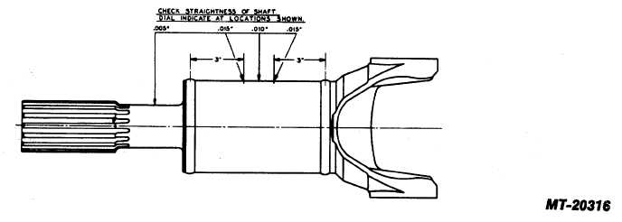
proceeding with final weld. After welding, the entire driveshaft
should be straightened to the following limits: (See Fig. 35)
.12 mm (.005") TIR
On shaft neck
.38 mm (.015") TIR
On ends of tubing 76.2
mm (3") from welds
.25 mm (.010") TIR
In center of tube
These run-outs should be taken with entire driveshaft
assembly mounted on master attaching flanges or yokes,
selected for dynamic balance to eliminate as much unbalance
as possible. During balancing, the driveshaft again should be
mounted on these selected flanges or yokes.
Fig. 35
CTS-2730 Page 18
PRINTED IN UNITED STATES OF AMERICA
|

