|
| |
TRUCK SERVICE MANUAL
TM 5-4210-230-14&P-1
PROPELLER SHAFT
SERVICE INSTRUCTIONS
ASSEMBLING UNIVERSAL JOINT MEDIUM AND HEAVY
DUTY (Figs. 21, 22 and 23)
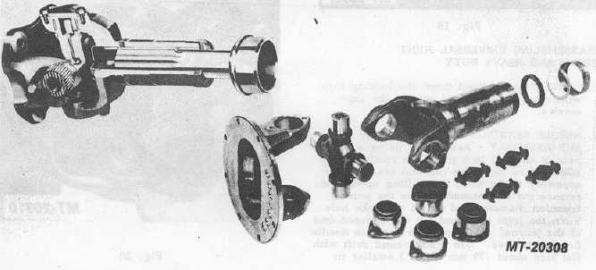
1.
SEAL If necessary to install a new kit make sure that
four new seals are installed in the journal retainers.
Fig. 21
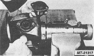
2. JOURNAL CROSS With the relief valve facing the
flange yoke, insert one trunnion of the journal cross
into the bearing hole in the yoke lug from the inside
between the lugs and tilt until the trunnion of the
journal cross will clear the hole in the opposite yoke
lug.
Fig. 22
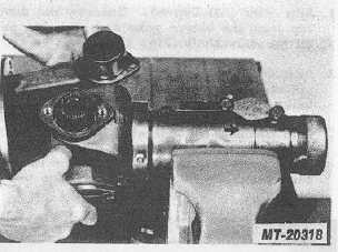
3.
NEEDLE BEARING AND RETAINING CAP SUB-
ASSEMBLY Insert from outside of yoke. Press into
place with an arbor press or tap with a soft round
drift taking care not to mar any surfaces.
4.
LOCK STRAP AND CAPSCREWS Assemble and
bend the lugs of the lock strap up against the flat of
the capscrew. If the joint appears to bind, tap the
lugs lightly to relieve any pressure of the bearing on
the end of the journal.
BEARING CAP CONSTRUCTION MEDIUM AND HEAVY DUTY
Fig. 23
CTS-2730 Page 14
PRINTED IN UNITED STATES OF AMERICA
|