|
| |
TRUCK SERVICE MANUAL
TM 5-4210-230-14&P-1
PROPELLER SHAFT
SERVICE INSTRUCTIONS
REMOVAL OF THE SLIP JOINT
1.
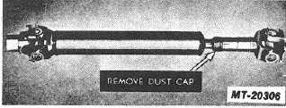
Slip Joint (All Types). Unscrew the dust cap from the
sleeve yoke and slide the joint off the driveshaft (Fig.
17).
2.
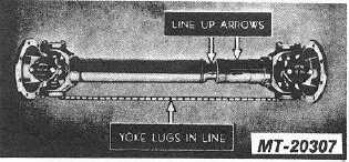
ARROW MARKS Make sure arrow marks are
stamped on the shaft and sleeve yoke before
removing the slip joint (Fig. 18). If arrow marks are
not readily seen, mark both members so that when
reassembled they will be in exactly the same relative
position, since' the sleeve yoke lugs must be in 'the
same plane as the stub ball yokes to prevent
excessive vibration.
Fig. 17
Fig. 18
DISASSEMBLING UNIVERSAL JOINT MEDIUM AND HEAVY
DUTY
1.
LOCK STRAP Bend down the locking lugs with a
screwdriver and remove the capscrews.
2.
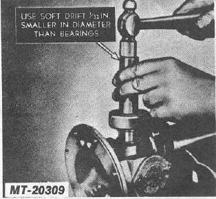
NEEDLE BEARINGS & RETAINING CAP SUB-
ASSEMBLY Remove by using a large pair of channel
lock pliers on retaining cap edges, turn retaining cap
and bearing subassembly at the same time lifting
upward to remove the sub-assembly from the journal
trunnion diameter and out of the yoke hole. Turn the
joint over and tap the exposed end of the journal
cross until the opposite needle bearing is free. Use a
soft round drift with flat face about .79 mm (1/32")
smaller in
diameter than the hole in the yoke, otherwise there is danger
of damaging the bearing (Fig.. 19).
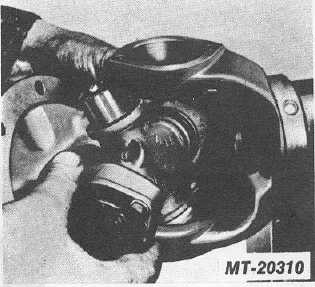
3.
JOURNAL CROSS Remove by sliding it to one side
of the yoke and tilting it over the top of the yoke lug
(Fig. 20).
Fig. 19
Fig. 20
CTS-2730 Page 13
PRINTED IN UNITED STATES O F AMERICA
|