|
| |
TRUCK SERVICE MANUAL
TM 5-4210-230-14&P-1
PROPELLER SHAFT
SERVICE INSTRUCTIONS
DISASSEMBLING UNIVERSAL JOINT
1.
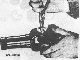
SNAP RING Remove by pinching the ends together
with a pair of pliers. If a ring does not readily snap
out of the groove in the yoke, tap the end of the
bearing cap lightly to relieve the pressure against the
ring (Fig. 24).
2.
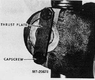
THRUST
PLATE
CONSTRUCTION
(Fig.
25)
Remove capscrews and plate. The balance of, the
disassembly and assembly instructions are the same
as those for snap ring joints.
3.
NEEDLE BEARING CAP Remove by driving on the
end of one bearing cap until the opposite bearing cap
comes out. Turn the joint over and tap the exposed
end of the journal cross until the opposite needle
bearing cap is free. Use a soft round drift with flat
face about .79 mm .(1/32") smaller than the hole
diameter in the yoke, otherwise, there is danger of
damaging the bearing.
Fig. 24
Fig. 25
4.
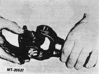
JOURNAL CROSS -Remove by sliding it to the side
of the yoke and tilting it over the top of the yoke lug
(Fig. 26).
Fig. 26
ASSEMBLING UNIVERSAL JOINT
Reassembly is merely reverse order of the above
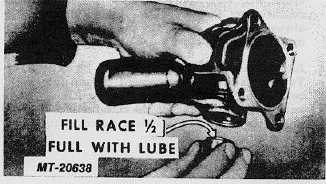
operations. On joints without a lubrication fitting, repack
reservoirs in the journal cross ends with the recommended
lubricant. Make sure the reservoir in each trunnion is filled.
With the rollers in the race, fill the race about 1/2 full (Fig.
27).
Fig. 27
U-BOLT CONSTRUCTION
U-Bolt joints are a combination of U-Bolt and snap
ring construction (Fig. 28). Except that the U-Bolts are
disassembled when the complete propeller shaft is removed
from the vehicle, the balance of disassembly and assembly
instructions are the same as those for snap ring joints.
CTS-2730 Page 15
PRINTED IN UNITED STATES OF AMERICA
|


