|
| |
TRUCK SERVICE MANUAL
TM 5-4210-230-14&P-1
PROPELLER SHAFT
SERVICE INSTRUCTIONS
Needle bearing joints are simple in construction, easily
removed from the vehicle and readily disassembled and
reassembled without the use of any special tools or any
special mechanical knowledge.
Fig. 13
REMOVAL FROM THE VEHICLE
1.
Double Flange, Yoke Types (Bearing Cap and Snap
Ring Construction)(Fig. 13)
All Double Flange Yoke Type Joints are removed as a
complete assembly by removal of the Companion Flange
Bolts, Nuts and Lockwashers, which allows the assembly to
slip out from between the Companion Flanges.
Fig. 14
2.
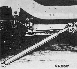
Double End, Yoke Type (U-Bolt (Construction) (Fig.
14)
Fig. 15
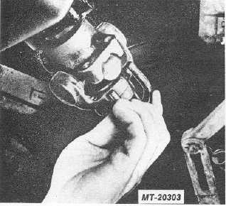
Remove the U-Bolts, Nuts, and Lockwashers from
the End Yokes. Slide the Sleeve Yoke toward the shaft to free
the Bearings from their seats between the shoulders in the
End Yokes (Fig. 15). Care should be taken not to drop the
two Bearings from the trunnion ends of the Journal Cross at
both ends of the driveshaft. The End Yokes remain on the
vehicle.
Fig. 16
3.
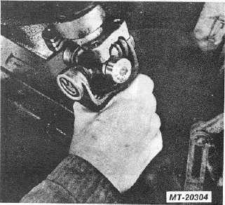
Double End Yoke Type (Bearing Cap Construction)
(Fig. 16)
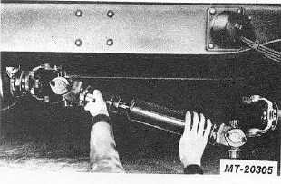
Remove the capscrews, lock plates and bearing and
retaining cap sub-assemblies, from the transmission and axle
end yokes. Remove the driveshaft with the remaining journal
crosses and bearings as a unit. The end yokes remain on the
vehicle.
CTS-2730 Page 12
PRINTED IN UNITED STATES OF AMERICA
|


