|
| |
TRUCK SERVICE MANUAL
TM 5-4210-230-14&P-1
INSTRUMENTS
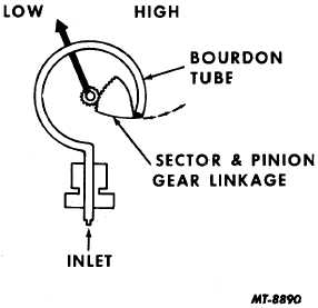
Fig. 23 Air Pressure Gauge Details
Remove
1.
Detach instrument cluster and cluster bezel.
2.
Unscrew air lines from fittings on rear of the two air
gauge inlets on back of instrument cluster.
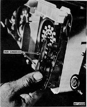
3.
Remove gauge mounting screws and demount gauges
from instrument cluster (Fig. 24).
Fig. 24 Removing Air Pressure Gauges
4.
Separate individual gauges from bracket.
Test
1.
If a suspected gauge has been reading high and does
not return to zero when disconnected, Bourdon tube
has been damaged. Service by replacing with a new
gauge.
2.
If gauge has been reading low or does not read at all,
examine the inlet connection for dirt which might
restrict air from entering gauge. Make a trial
connection and if gauge still does not register correctly,
replace gauge.
IMPORTANT
Always make a comparison test with a gauge
known to be reading correctly before discarding
a questionable gauge.
Install
Installation of air gauges is the reverse of removal
procedure. Be sure to use non-hardening sealing compound on
fitting threads to prevent leaks. Check installation so as to
prevent kinks in air lines.
VOLTMETER
The voltmeter or battery-charging system gauge (Fig.
25) indicates the condition of battery and charging system.
This gauge will monitor a voltage range between 10 and 16
volts. Color segments of this range also indicate system
condition as follows:
GREEN - A well charged battery.
FIRE ORANGE - Either a too high or too low charged
battery.
With key switch "on" but before starting engine, the
voltmeter will show condition of battery. While starting engine,
indicator will temporarily descend to "Fire Orange" segment but
immediately return to "Green" segment when engine is
operating. With engine running at operating speeds, the
voltmeter indicator should remain in the "Green" segment. This
is charging system's normal operating range and indicates
alternator is charging.
If indicator ascends to "Fire Orange" segment, alternator
voltage output is too high.
Constant reading in either high or low fire orange
segments of the voltmeter indicates a
CTS-2735R Page 14
PRINTED IN UNITED STATES OF AMERICA
|