|
| |
TRUCK SERVICE MANUAL
TM 5-4210-230-14&P-1
INSTRUMENTS
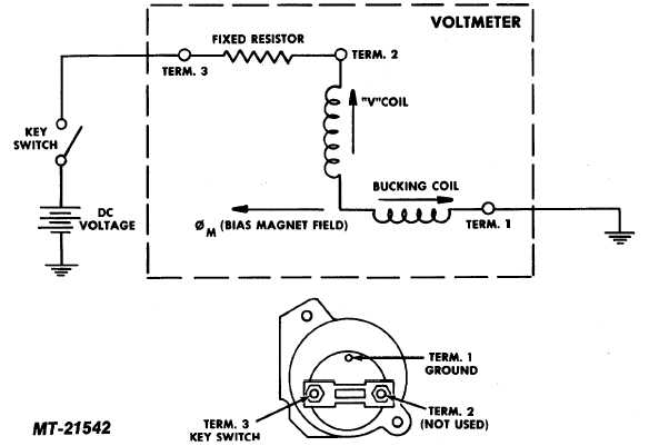
Fig. 25 Voltmeter Circuit Diagram
complete check of battery and charging system is
required. See appropriate alternator section of Service
Manual under ELECTRICAL.
If voltmeter does not read as expected, you can
check operation of this instrument by connecting
voltmeter terminals to an independent voltage source
(12V Battery). The voltmeter should indicate the
voltage supplied by battery 0.5 volts.
If test is unsatisfactory, replace voltmeter.
If test is satisfactory, voltmeter is OK and
problem is in wiring. Check continuity with test light.
GAUGE TESTING (TABLE A)
A summary of necessary gauge testing specifications is
given in "Table A". When the service man becomes
familiar with the SE-2781 Gauge Tester, this table will
provide a handy reference.
QUICK CHECK (TABLE B)
If a universal gauge tester is not available,
electrical gauges can also be "quick checked" to
determine if they are functioning by a simple "Sender
Disconnect and Ground Test", that is sometimes used
for automotive gauge testing. While this is a quick test,
it does have two disadvantages.
1. The test tells only that gauge is functioning.
It does not determine if gauge is accurate.
2. The grounding of sender wire test for a
temperature gauge will damage that unit.
CTS-2735R Page 15
PRINTED IN UNITED STATES OF AMERICA
|