|
| |
TRUCK SERVICE MANUAL
TM 5-4210-230-14&P-1
INSTRUMENTS
IMPORTANT
Sometimes sealant or dirt on threads of sender
(thermister) prevent a good electrical contact
necessary for sender grounding. Check for this
condition before replacing sender.
If results of Steps 3 thru 5 are unsatisfactory check
continuity of circuit with a standard test light. If continuity is OK
and gauge still does not respond, replace gauge.
OIL PRESSURE GAUGE
The oil pressure gauge is electrically actuated and
consists of two basic components--the instrument cluster
mounted gauge and the engine oil gallery mounted sending
unit. The sending unit: senses the pressure of oil in the engine
oil gallery during engine operation and registers the pressure on
the gauge.
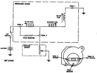
The operation of the oil pressure gauge system (Fig. 21)
is the same as for fuel level gauge except that sender is a
diaphragm unit in oil gallery instead of a float.
Testing for a defective oil pressure system component is
also the same. See FUEL LEVEL GAUGE for testing
procedure.
Fig. 21 Oil Pressure Gauge Circuit Diagram
OIL PRESSURE WARNING LAMP
A second or back-up oil pressure warning system is also
used. This system uses a second oil pressure warning switch
mounted on the engine.
When engine oil pressure is in its normal operating range
(high) the pressure switch is held in its off position and no
current is sent to warning light in the instrument cluster.
When engine oil pressure is below its normal operating
range (low) the pressure switch will close to its "on" position and
deliver current to warning light in instrument cluster and cause
warning lamp to light. OPTIONAL TEMPERATURE GAUGE
The optional temperature gauges (Fig. 22) are also
electro-magnetic type and are actuated by sending units
(variable resistance thermisters). Sending units are located in
the component on which temperature monitoring is desired
(engine, transmission, rear axles, etc. )
Operating and testing of optional temperature gauges is
the same as for comparable temperature systems previously
covered. See SPECIFICATIONS for variable resistance value
(ohms) required for checking these gauges.
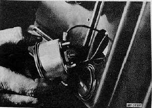
Fig. 22 Servicing Optional Gauge
AIR PRESSURE GAUGE
The air pressure gauges are the mechanical type and
operate on the Bourdon tube principle.
When air system is pressurized, air enters the air
pressure gauge and exerts pressure on the Bourdon tube. As
pressure increases, the Bourdon tube tends to straighten out
and thus actuate the sector and pinion gear (Fig. 23) to which it
is attached. This causes indicator to move across dial in an
upscale direction. When pressure decreases, the Bourdon tube
relaxes and pointer moves in a downscale direction. A steadily
applied air pressure holds the Bourdon tube and pointer at a
fixed
scale
reading
corresponding
to
applied
pressure.
CTS-2735R Page 13
PRINTED IN UNITED STATES OF AMERICA
|