|
| |
TRUCK SERVICE MANUAL
TM 5-4210-230-14&P-1
INSTRUMENTS
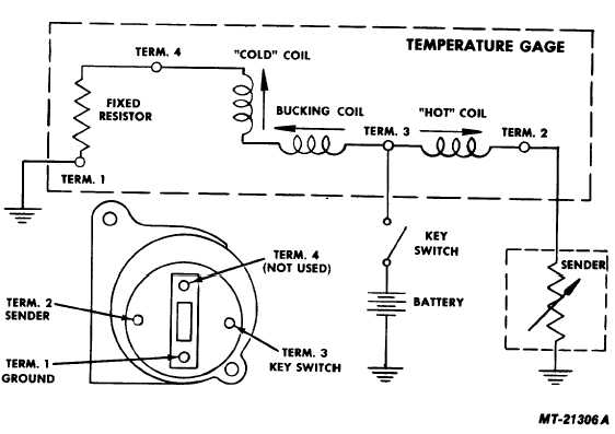
Fig. 20 Water Temperature Gauge Circuit Diagram
temperature coefficient. The decrease in sender resistance
increases the current flowing in the "hot" coil, reaching a
maximum at the full-scale temperature. With maximum current
in the "hot" coil, the pointer and armature assembly will align
itself with the resultant magnetic field produced by the three
coils at the full-scale position. Thus, the interaction of the
magnetic fields of the three coils produces a resultant magnetic
field which controls the rotation and position of the armature
and pointer assembly.
IMPORTANT
The gauge is grounded to chassis through the
ground
terminal
when
plugged
into
the
instrument cluster printed circuit.
The sender terminal is the first terminal clockwise from
ground terminal (when viewed from back side). The ignition
terminal is directly opposite from sender terminal.
Check for faulty components as follows:
1.
Disconnect sender wire at sender (Fig. 20).
2.
Connect one lead of SE-2781 Gauge Tester to sender
wire and the other lead to a good ground.
3.
Set the gauge tester for 55 ohms (left knob at "50" and
right knob at "5"). Turn key switch on and. gauge
should read at full scale. (Pointer within 2 pointer
widths of hash mark).
4.
Set gauge tester for 113 ohms (left knob at 100 and
right knob at 13 ohms). Gauge should read at half
scale. (Pointer within 2 pointer widths of hash mark).
5.
Set gauge tester for 1365 ohms (center knob at "1365"
and other knobs at "O"). The gauge should now read
at low scale. (Pointer within 2 pointer widths of hash
mark).
If results of Steps 3 thru 5 are satisfactory gauge is OK
and sender must be replaced.
CTS-2735R Page 12
PRINTED IN UNITED STATES OF AMERICA
|