|
| |
TRUCK SERVICE MANUAL
TM 5-4210-230-14&P-1
INSTRUMENTS
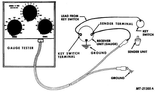
Fig. 19 Checking Fuel Level Gauge System with Gauge Tester
Test for faulty component as follows.
1.
Disconnect wire at tank sender unit (Fig. 19).
2.
Connect one lead of SE-2781 Gauge Tester to end of
sender unit wire and second lead to ground (tester
substitutes for sender unit).
3.
Turn key switch "on".
4.
Set gauge tester for 88 ohms (left hand control knob to
"50" and right hand knob at "38"). Fuel gauge should
read slightly above "full". (Pointer within ball).
5.
Next set left hand knob at "0" and right hand knob at
"44". Fuel gauge should read at "1/2" mark. (Pointer
within ball).
6.
Finally set left hand knob at "0" and right hand knob at
"1". Gauge should now read "empty". (Pointer within
ball).
If fuel gauge reads properly, gauge and wiring between
gauge and sender is OK and trouble is in sender grounding or
sender itself. Replace float assembly if proper grounding does
not correct the problem.
If fuel gauge does not read properly, check continuity of
circuit with standard test light (Fig. 12). If continuity is OK and
gauge still does not respond, replace gauge.
WATER TEMPERATURE GAUGE
The water temperature gauge system consists of two
basic components--the instrument cluster gauge and the
thermister sending unit. The gauge indicates water temperature
while the sender controls the gauge reading. The two units are
connected electrically as shown in Fig. 20.
The operating principle of the temperature indicating
system can be understood by reference to the temperature gage
circuit diagram (Fig. 20). With the ignition switch closed,
current will flow from the battery through the bucking and "cold"
coils and the fixed resistor to ground, and through the "Hot" coil
and the variable resistance temperature sender to ground.
The temperature sender consists of a thermistor
enclosed in a sealed threaded shell containing a heat transfer
medium and equipped with an insulated terminal. With the
temperature sender immersed in a cold liquid (1000F), its
resistance is high and the current flowing through the "hot" coil
is small; therefore, the magnetic field produced by the "hot" coil
is negligible. At this time the pointer and armature assembly
will align itself with the resultant magnetic field produced by the
"cold" and bucking coils at the 1000 F position. The magnetic
field of the "cold" and bucking coils is always a constant and
serves as a reference. As the temperature of the liquid
increases, the resistance of the sender decreases since the
thermistor has a negative temperature
CTS-2735R Page 11
PRINTED IN UNITED STATES OF AMERICA
|