|
| |
TRUCK SERVICE MANUAL
TM 5-4210-230-14&P-1
INSTRUMENTS
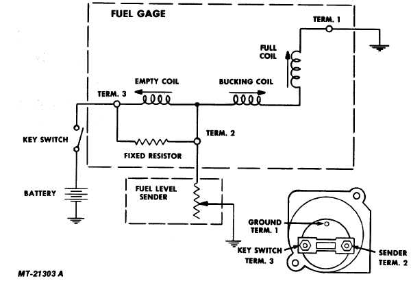
Fig. 17 Fuel Gauge Circuit Diagram
- the fuel level sender only when in its empty position.
It will be noted that variations in the position of the fuel
level sender contact will vary the active portion of resistance
element and thus control the amount of current flowing in the
bucking and full coils. Maximum current in the bucking and full
coils occurs with the tank unit in the full "F" position. Under this
condition, the magnetic field of the bucking and full coils is at
maximum and the pointer and armature assembly will align
itself with the resultant magnetic field of the three coils the "Full"
position. As the fuel is used, the fuel level sender contact
position changes to reduce the current in the bucking and full
coils and increases the current in the empty coil. This variation
in current reduces the magnetic field strength of the bucking
and full coils from a maximum at "full" to zero at the empty or
"E" position at which time the armature and pointer assembly is
aligned with the magnetic field of the empty coil. Thus, the
interaction of the magnetic field of the three coils produces a
resultant magnetic field which controls the rotation and position
of the armature and pointer assembly.
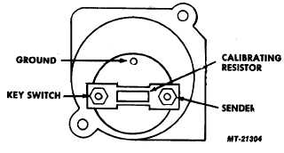
The sender and key switch terminals are connected by a
calibrating resistor (Fig. 18). The odd terminal is the ground
terminal.
The sender terminal is the first terminal clockwise from
ground terminal when viewed from back side of gauge.
IMPORTANT
The gauge is grounded to chassis through the
ground terminal when plugged into instrument
cluster printed circuit.
When the key switch is turned off, pointer will not
necessarily return to the empty position. This is inherent in the
instrument and does not indicate a faulty part.
Fig. 18 Fuel Gauge (Rear View)
CTS-2735R Page 10
PRINTED IN UNITED STATES OF AMERICA
|