|
| |
TRUCK SERVICE MANUAL
TM 5-4210-230-14&P-1
INSTRUMENTS
2.
Feed the core (lower end first) through the lube and
into casing.
3.
Keep last four inches of cable free of lube to prevent
lube from entering the instrument head.
4.
Install complete cable assembly in chassis and
connect in reverse order of "Removal" procedure.
IMPORTANT
Avoid sharp bends when installing speedometer
or tachometer cables. Under no circumstances
should a casing have less than a six-inch radius
bend. Route tachometer cable away from
compressor discharge line and strap to stay rod
to avoid cable damage.
GAUGE OPERATION TROUBLE SHOOTING
Except for air pressure gauges which are mechanical--
Bourdon tube type--all gauges are of the electro-magnetic air
core type. In each system to be monitored (Fuel Level, Oil
Pressure, Water Temperature, etc.) a sender uses a variable
resistance to control current from the battery through a coil or
coils in the gauge.
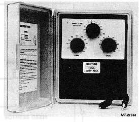
Gauge Tester
To assist in checking the electrical indicating type gauges
a simple test procedure using a universal type Gauge Tester
SE-2781 (Fig. 16) is suggested. This testing instrument
eliminates time consuming trial and error methods of checking
out the gauges.
IMPORTANT
To insure full power to all instruments in cluster,
connector lock tabs on both sides of harness
connector, must be solidly engaged with cluster
socket.
Proper connector insertion and power to cluster
is assured if the following indicators react when
key switch is turned on:
1. Voltmeter pointer moves up scale.
2. Warning lights (except Anti-Lock) come on.
With power to cluster off, gauge pointers may
move to any point on gauge scale. This is
inherent to instrument and does not indicate a
faulty part.
Fig. 16 Gauge Tester (SE-2781)
Test Application
Gauges can be tested on vehicle, without detaching them,
by removing sender to gauge wire at sender unit and connecting
in the SE-2781 Gauge Tester. Test continuity on gauge circuits
with the SE-2060-4 Test Light. Details of this procedure are
covered in later paragraphs.
FUEL LEVEL GAUGE
The electric fuel gauge system consists of two basic
components--the instrument cluster mounted gauge and the
fuel tank sending unit. The tank unit controls the gauge and the
gauge registers the quantity of fuel in the tank. The two units
are connected electrically as shown in Fig. 17.
This air core type fuel gauge consists of three (3) copper
wire coils wound around a plastic bobbin containing a magnet
and spindle assembly. Attached to the magnet and spindle
assembly is a pointer which indicates fuel level. The fuel gauge
requires a 0 to 90 ohm resistance sender to operate. The
sender is the tank unit and consists of a float and arm assembly
and a variable resistor. The sender's resistance is controlled by
the position of float and arm assembly. A full fuel tank raises
float to its highest position. At this position the variable resistor
has a resistance of 88 ohms. With an empty fuel tank the float
assumes its lowest position, creating a sender resistance of
less than 1 ohm.
The fuel gage circuit diagram (Fig. 17) shows that with
key switch "ON", current flows from the battery through a
parallel circuit consisting of the empty coil and the fixed resistor
and thence through another circuit composed of:
- the variable resistance fuel level sender and the bucking
coil and the full coil.
CTS-2735 Page 9
PRINTED IN UNITED STATES OF AMERICA
|