|
| |
TROUBLE SHOOTING
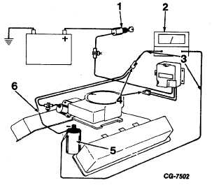
Figure 64 Step 3
1.
Ignition Switch “OFF”
4.
ECU Terminals
2.
Ohmmeter
5.
Ignition Coil
3.
Meter Leads
6.
Engine Speed Signal to ECU
Cable
b.
If normal, reconnect cable and proceed to next step.
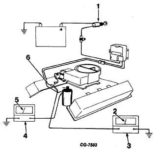
CG-7503. Figure 65 Step 4
1.
Ignition Switch “ON”
4.
Tachometer
Engine Running
5.
Governor Speed
2.
Battery Voltage
6.
ECU to Solenoid Cable
3.
Voltmeter
4.
Disconnect cable terminal connector between ECU
and solenoid valve (on carburetor). Connect
tachometer and voltmeter. Start engine, increase
speed until governor no load rpm is reached (see
specifications). Battery voltage should be obtained
at ECU side of connector.
a.
If battery voltage is not obtained, replace ECU.
b.
If battery voltage is obtained, stop engine and
proceed to next step.
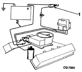
Figure 66 Step 5
1. Ignition Switch “OFF”
2. Jumper Wire CG-7505
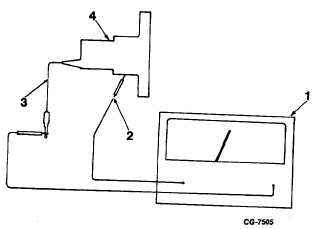
Figure 67. Step 5b
1.
Ohmmeter
3.
Solenoid Cable
2.
To Solenoid Case
4.
Solenoid Assembly
CGES-125-T Page 42
PRINTED IN UNITED STATES OF AMERICA
|