|
| |
ENGINE DIVISION SERVICE MANUAL
TM 5-4210-230-14&P-1
TROUBLE SHOOTING
ELECTRONIC VACUUM MODULATING (EVM) GOVERNOR
SYSTEM TROUBLE SHOOTING PROCEDURE
The following procedure presents a J systematic
method of diagnosing and trouble shooting the Electronic
Vacuum Modulating (EVM) Governor System. Each trouble
shooting step has a chart to locate the component and
illustrate the test. Test instruments used consist of a volt-
meter and a tachometer.
It is recommended that the tachometer used for
testing governor no load speed be an instrument with a high
percentage of accuracy. The governed no load speed should
be within a 100 RPM tolerance.
If engine speed reading is more than 100 RPM high
or lower than the specified governed no load speed, make
sure the tachometer being used has been properly calibrated
before condemning the ECU or vacuum solenoid valve.
Figure 61 Anti Tamper Proof Seal
Electrical connections on the EVM system are sealed
with an anti-tamper proof seal tape which is placed on the
connectors at the time of assembly. The production seal tape
can be identified by its white color with black print. If the
connector seal tape is tampered with the word VOID will
appear.
After service is performed, a service anti-tamper
proof tape which is white in color with red print should be
installed. This difference in print color will show the system
has been serviced.
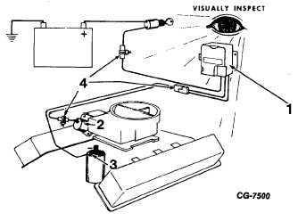
1. Visually inspect condition of wiring connections and
components.
2. Disconnect wire at electronic control unit (ECU).
Check for battery voltage with ignition turned on. If
battery voltage is not found, refer to Service Manual,
ELECTRICAL, for repair. If battery voltage is found,
proceed to Step 3.
Figure 62. Step 1
1. Electronic Control Unit (ECU)
2. Solenoid Vacuum Valve
3. Ignition Coil
4. Cable Connections Figure
Figure 63. Step 2
1. Ignition Switch “ON”
2. Battery Voltage
3. Volt Meter
4. Battery Source to ECU Cable
3.
Disconnect ECU signal cable at terminal
connector as shown.
a. Check continuity of cable from negative side
of coil to ECU end. If reading indicates an
open circuit, replace cable.
CGES-125-T Page 41
ENGINE DIVISION SERVICE MANUAL
TM 5-4210-230-14&P-1
|