|
| |
TRUCK SERVICE MANUAL
TM 5-4210-230-14&P-1
ADJUSTMENT PROCEDURE
NOTE: Record the number of turns it takes
to increase or decrease the engine RPM to
the specified speed shown:
V-392
2000 RPM
MV-404, 446
2400 RPM
V-537, 605
2000 RPM
4. Run curb idle stop screw in until it contact the internal
stop.
5. Release choke as it opens completely.
6. Start engine, observe and record (RPM) tachometer
reading. If RPM reading does not correspond with fast idle
speed specification chart, an adjustment should be made.
7. To increase RPM, continue to turn the curb idle screw until
proper fast idle speed is reached (See Fig. 53).
8. Before shutting off engine back out curb idle screw until
engine speed is reduced to curb idle speed to prevent engine
dieseling. Shut off engine (See Fig. 42).
9. Depress accelerator pedal to floor. Close choke and
release accelerator pedal.
Figure 54 Adjusting Fast Idle Screw With SE-1772-18
Wrench
10. Reset curb idle screw until it lightly contacts the inner
stop. Turn the idle screw in the number of additional turns
recorded (in Step 8) to reach proper fast idle speed setting.
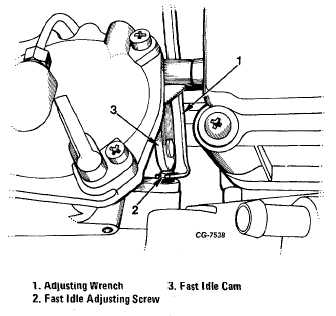
11. Adjust fast idle screw with special wrench SE-1772-18
until the screw just contacts the fast idle cam (See Fig. 54).
Contact is established when visual clearance between the
screw and the cam is eliminated or when the throttle lever
starts to move.
12. To recheck adjustment, choke closed, back out idle screw
two turns and then reset screw until lightly contacting internal
stop.
13. Open choke, start engine, proper engine RPM should now
be obtained.
14. Repeat Step No. 9.
15. Reinstall spring on idle speed screw and install screw
with spring.
16. Reinstall air cleaner and adjust proper curb idle speed
(See Specifications).
Idle Speed and Fuel Mixture Adjustment Procedure Without
Exhaust Analyzer (Speed Drop Method)
1. Connect tachometer to engine (Tachometer should have
expanded scale of 400-800 RPM or 0-1000 RPM and 1%-2%
accuracy.)
2. Turn idle mixture screw(s) "out" (counterclockwise) against
tab stop.
NOTE: If working with a unit rebuild which
has not had the idle limiter caps installed,
refer to specification for the initial idle
setting.
3. Operate engine until thoroughly warmed up.
4. Adjust idle speed screw to give engine speed higher than
specified idle speed. (See "Specifications".)
5. Turn idle mixture screws "in" (clockwise) slowly and
equally until specified idle speed is obtained. The resulting
idle fuel mixture is optimum for exhaust emission control.
NOTE: If working with unit rebuild, install
idle limiter caps at this time.
6. If engine runs rough after obtaining specified idle speed or
if specified idle speed cannot be obtained (per Steps 4 and 5),
it will be necessary to remove the idle limiter caps and
establish proper mixture screw setting as follows:
a. Remove limiter caps. To prevent damaging screw threads
or seat, file or grind away the side of the cap. Do not pry cap
off.
b. With engine operating, adjust mixture screws to obtain
"lean best idle" at the specified idle speed. ("Lean best idle" is
the point at which engine speed drops approximately 10 RPM
due to leanness.)
CGES-125-T Page 36
PRINTED IN UNITED STATES OF AMERICA
|