|
| |
TRUCK SERVICE MANUAL
TM 5-4210-230-14&P-1
ADJUSTMENT PROCEDURE
INSTALLATION AND ADJUSTMENTS
Off Engine Fast Idle Adjustment
If the carburetor was removed from the truck for replacement
or overhaul procedures, it is recommended that a preliminary
fast idle adjustment be performed as follows.
1. After carburetor is completely assembled open throttle with
throttle lever and close the choke plate.
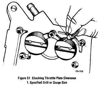
2. Invert carburetor. Insert gauge (from gauge set SE-2425
or drill of same diameter) upstream between throttle plate and
throttle body of the primary bore (see Fig. 51).
Figure 51 Checking Throttle Plate Clearance
Fast Idle Throttle Plate Clearance
Engine Speed
(Gauge or Drill Sizes)
V-392 2000 RPM
.040
MV-404 2400 RPM
.045
MV-446 2400 RPM
.045
V-537 2000 RPM
.045
V-605 2000 RPM
.045
3. With gauge or drill held in place by the primary throttle
plate against the bore, adjust the fast idle screw until the
screw touches the cam lightly (see Fig. 54).
4. The gauge-or drill size dimension for the throttle plate
clearance and fast idle speed are given above:
5. After the carburetor is installed on the engine, warm
engine to operating temperature, connect tachometer and
check fast idle reading with above specifications.
Installing Carburetor on Engine
Always make a thorough inspection of the carburetor before
installing on the engine. Operate the choke and throttle levers
to be sure choke and throttle plates function properly. Make
sure unit is clean and undamaged in any way. Mating surface
of intake manifold must also be <-f clean and free of burrs
or damage. Use a new flange gasket and secure the
carburetor to the intake manifold with mounting nuts and lock
washers. Do not tighten nuts all the way down. Connect the
fuel line, distributor vacuum line, governor lines (where used)
and throttle and choke linkage. Tighten mounting nuts
alternately and evenly in a criss-cross pattern to compress
flange gasket. Draw nuts down tightly.
Loading the Throttle Redundant Safety Spring
Loading the linkage is accomplished by rotating the throttle
lever to wide open throttle by moving accelerator control rod
to the right. Do not rotate throttle lever directly, since it will
snap to the closed position, then attach throttle return spring
to the trip lever. Secure opposite end of throttle return spring
to throttle return spring anchor bracket. Slowly return throttle
lever to idle position.
CAUTION
Whenever throttle return spring is disconnected at either
end, the throttle linkage at the carburetor will snap to the
closed position with a spring force sufficient to cause
possible personal injury.
ON ENGINE ADJUSTMENTS
Fuel Level Adjustment
Position the truck on a level floor. Be sure the fuel pump
pressure is within specifications. Operate the engine until the
normal, stabilized operating temperature has been reached.
Place a suitable container below the fuel level sight plug to
collect any spill-over of fuel. Check each fuel bowl separately.
With the engine stopped remove the air cleaner assembly,
fuel level sight plug and gasket and check the fuel level (Fig.
52). The fuel level within the bowl should be at the lower edge
of the sight plug opening + 1/32". If the fuel level is
satisfactory, install the sight plug.
CGES-125-T Page 34
PRINTED IN UNITED STATES OF AMERICA
|