|
| |
TRUCK SERVICE MANUAL
TM 5-4210-230-14&P-1
DISASSEMBLY
Main Body
1. Remove the air cleaner anchor stud and remove the
secondary control valve tube located between governor
and secondary control valve.
2. Remove the choke control lever and the governor housing
cover.
3. Remove the nut and lock washer retaining the governor
lever to the throttle shaft, then remove the governor
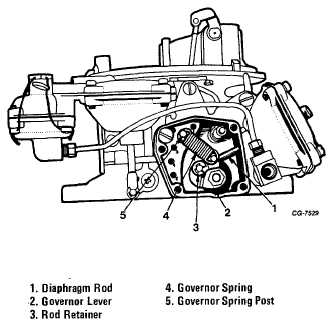
housing assembly (Fig. 35).
4. Remove the secondary diaphragm link retainer.
Figure 35 Interior View of governor Housing
5. Invert the carburetor and remove the throttle body to main
body screws and lock washers. Lift off the main body and
remove the main body gasket. Discard the gasket.
6. Remove the retainer securing the choke rod to the choke
rod lever and bushing assembly, then remove the lever
retainer and remove the lever and lever spring.
7. Remove the secondary diaphragm housing and gasket
from the main body.
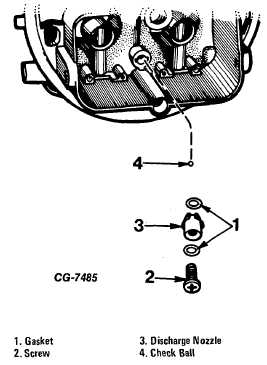
8. Remove the accelerating pump discharge nozzle screw,
then lift the pump discharge nozzle and gasket out of the main
body. Invert the main body and let the discharge ball fall into
the hand (Fig. 36).
Figure 36 Removing Pump Discharge Check Ball (4150 and
4150C Only)
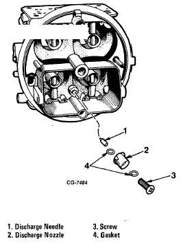
9. Models 4150G and 4150EG use a pump discharge needle
in lieu of a ball as shown in Fig. 37.
Figure 37 Removing Pump Discharge Needle (4150G and
4150EG Only
)
CGES-125-T Page 24
PRINTED IN UNITED STATES OF AMERICA
|