|
| |
TRUCK SERVICE MANUAL
TM 5-4210-230-14&P-1
DISASSEMBLY
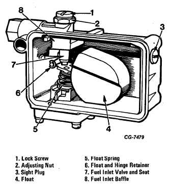
7. Remove the fuel level adjustment lock screw and gasket.
Turn the adjusting nut counterclockwise and remove the lock
nut and gasket. Remove the fuel inlet needle and seat
assembly. Do not disassemble the fuel inlet needle and seat.
They are matched assemblies and are replaced as an
assembly (Fig. 32).
1.
Figure 32 Fuel Bowl and Components
8. Remove the fuel level sight plug and gasket.
9. Remove the fuel inlet fitting, gasket and filter screen.
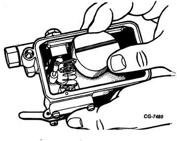
Figure 33 Removing Float and Hinge Assembly
10. Remove the baffle plate from the fuel bowl.
11. Using needle nose pliers, remove the float retainer (Fig.
33). Slide the float (noting color) off the shaft.
Remove the spring from the float.
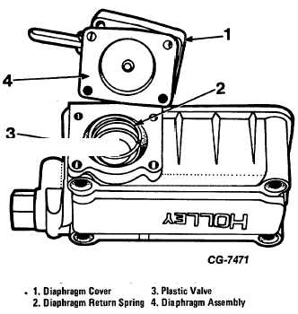
12. Remove the four pump diaphragm cover screws. Lift off
the pump diaphragm cover, diaphragm assembly and
return spring (Fig. 34). If it is necessary to remove the
accelerator pump synthetic valve (where used), grasp it
firmly and pull it out. If the valve tip breaks off during
removal, be sure to remove the tip from the fuel bowl.
Removal of the valve necessitates replacement with a
new valve.
13. Remove the secondary fuel bowl and gasket and the
metering block and gasket. Discard the gaskets.
14. Remove the following parts from the secondary metering
block: Using a jet wrench, SE-1772-6, remove the main
jets (Fig. 31). Using a socket wrench, SE-1772-1,
remove the power valve and gasket (where used).
Discard the gasket. Remove the idle adjusting needles
and gaskets. Discard the gaskets (Fig. 31).
15. Disassemble the secondary fuel bowl by following Steps
7, 8, 9, 10 and 11. Refer to Fig. 28 for complete
disassembly of fuel bowl and metering block.
CGES-125-T Page 23
PRINTED IN UNITED STATES OF AMERICA
|


