|
| |
TRUCK SERVICE MANUAL
TM 5-4210-230-14&P-1
DISASSEMBLY
10. Lightly scribe a mark along the choke shaft on the choke
plate to insure proper positioning of choke plate during
reassembly.
11. File off the staking from choke plate retaining screws to
prevent damaging choke shaft threads during screw removal.
Remove the two choke plate screws and slide choke plate out
of choke shaft.
12. Slide choke shaft out of main body. Use new screws
during reassembly. Throttle Operating Housing
1. Straighten lock tab on throttle operating shaft nut lock and
remove nut, lock and washer.
2. Hold redundant spring concentric with throttle operating
shaft and remove spring drum.
3. Remove "spacer" washer.
4. Release redundant spring from long spring perch and
remove redundant spring.
5. Remove catch lever bushing and pin assembly.
6. Remove trip lever.
7. Remove accelerator pump operating lever assembly
retainer.
8. Remove the two throttle operating housing screws and
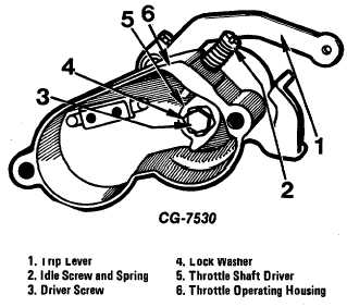
remove housing assembly (Fig. 38).
Figure 38 Throttle Operating Housing Assembly
9. Straighten lock tabs on throttle operating driver (inside
throttle operating housing). NOTE: Position the flats of the
throttle shaft driver in relation with the idle adjusting screw.
10. Remove operating lever and shaft assembly.
11. Remove pump cam retainer screw, noting hole position
and reference number on cam and lever. The cast numbers
on the cam are facing toward the throttle operating housing.
Then remove cam (do not put cam in carburetor cleaner).
12. Remove the (hot engine) idle screw and spring.
Governor Housing
1. Remove and discard the governor housing seal.
2. Mark the governor spring pin hole to facilitate assembly.
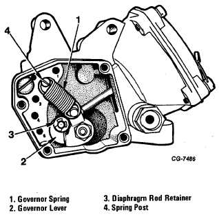
Remove the spring and pin if damaged (Fig. 39).
Figure 39 Interior View of Governor Housing
3. Remove the diaphragm rod retainer and governor lever.
4. Remove the governor line fitting. Make a note of the
governor bypass jet numbers and their positions. Remove the
bypass jets, the diaphragm cover and the diaphragm.
5. Remove the fast idle camshaft retainer and slide the fast
idle cam and shaft out of the housing.
6. Remove the cam plunger, spring and fast idle pin.
CGES-125-T Page 25
PRINTED IN UNITED STATES OF AMERICA
|


