|
| |
ENGINE DIVISION SERVICE MANUAL
TM 5-4210-230-14&P-1
ENGINE
coolant directed to the radiator is modulated by the thermostat
that opens the outlet to the radiator and reduces the orifice
size of the coolant bypass. Figure 136.
Secondary cooling systems include the engine oil
cooler, chassis heater and air compressor.
The oil cooler is mounted at the lower left corner of
the crankcase. The coolant flows from the left bank
crankcase water jacket through the cooler and into crankcase
inlet area. The amount of coolant flowing through the cooler
is metered by the diameter of the outlet hole on the oil cooler
housing.
Coolant for the air compressor is tapped off the front
of the cylinder head, left bank, flows through the air
compressor and back into the crankcase coolant inlet casting.
Coolant for the chassis heater is picked up off the
rear of the right cylinder head and returned to the suction side
of the coolant pump.
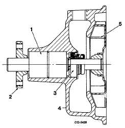
The centrifugal water pump is serviced only as a
complete assembly, Figure 137.
Fig. 137 Section View of Water Pump Assembly
1. Bearing assembly
4. Housing
2. Pulley hub
5. Impeller
3. Seal
Engine Assembly
1.
With the cylinder block attached to the engine repair
stand, turn the block on the stand so the bottom faces
upward. Make sure the drain plugs are installed in the
cylinder block if they have been removed.
2.
Coat the camshaft lobes, bearing surfaces, gears and
bores with engine oil.
3.
Install camshaft into bore with fuel pump cam, distributor
drive gear, camshaft gear and thrust flange installed on
shaft.
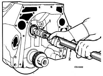
NOTE: If gears and fuel pump cam have been removed,
use SE-1880 installer and SE-1880-2 adapter to install
camshaft, Figure 138. This will help prevent nicking or
other damage to the camshaft bearings. Install
distributor drive gear, fuel pump cam and camshaft gear
as outlined under Camshaft Engine Overhaul.
Fig. 138 Use of SE-1880 Camshaft Installer and SE-188G-2
Adapter
1. Camshaft
2. Installer
4.
Install two bolts and lockwashers in camshaft thrust
flange, working through the holes in the camshaft gear.
See "Torque Chart" for proper torque.
5.
With the use of a dial indicator, check the camshaft end
play, Figure 139. See "Specifications." If-the end play
exceeds the limits, replace the camshaft thrust flange.
CGES-210 Page 56
PRINTED IN UNITED STATES OF AMERICA
|