|
| |
ENGINE DIVISION SERVICE MANUAL
TM 5-4210-230-14&P-1
ENGINE
Oil Pan
The pan should be thoroughly cleaned in cleaning
solvent to remove any foreign material from around the baffle
plate which is spot welded in place. Inspect oil pan for cracks
or deformation and straighten or weld.
Remove all gasket material from the oil pan flange.
Check the oil pan drain plug boss for fit and thread
wear. If the plug is loose or the threads are damaged, repair
the threads or replace the oil pan.
Manifolds
The intake manifold is cast in one piece and supplies
both cylinder banks. It should be cleaned and examined for
cracks or leaks. Warpage of the intake manifold will require
replacement as any attempt to resurface the intake manifold
will create misalignment of the ports to the cylinder heads.
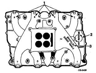
The intake manifold also contains the direction of distributor
rotation, firing order and the cylinder numbers Figure 135.
Fig. 135 Illustration of Information Contained on Intake
Manifold
1. Cylinder number
2. Direction of distributor rotation
3. Firing order
Each bank has a separate exhaust manifold which
should both be cleaned and examined for cracks or leaks.
Flywheel and Ring Gear
Clean the flywheel and ring gear with a cleaning
solvent, removing all traces of oil and grease. Inspect the
flywheel ring gear. If any teeth are damaged or if the ring
gear
is
loose
on
the
flywheel,
the
ring gear must be replaced. Check the flywheel mounting bolt
holes for wear; also check mounting face of flywheel for
indication of looseness.
To replace the flywheel ring gear, heat the gear with
a torch and remove it from the flywheel with a' hammer and
drift Heat the new ring gear evenly all the way around with a
torch. While the ring gear is hot, install the gear on the
flywheel and allow it to cool.
Water Pump and Coolant Flow
Coolant enters the engine at the lower left hand
corner of the crankcase. The coolant then flows into the water
pump where it is mixed with a quantity of bypassed hot
coolant. The water pump discharges into both the right and
left of the crankcase. The circulation of the coolant is from
front to rear of the crankcase, then flows up into the cylinder
head via three holes. The flow continues forward through the
cylinder head. In flowing through the cylinder head the coolant
is forced through a zig-zag path to insure maximum scrubbing
of critical areas of the cylinder head such as exhaust valve
seats and spark plugs.
The coolant exits the cylinder heads into a common
cavity at the front of the crankcase. Temperature sending unit
is located in this cavity. From this cavity the coolant flows
into the chassis radiator or back into the water pump via a
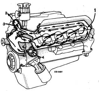
variable orifice bypass. The amount of
Fig. 136 Coolant Flow Cut-Away
1. Full pressure flow to rear of crankcase-up-and to front of lead.
2. Outlet
3. Bypass
4. Inlet
CGES-210 Page 55
PRINTED IN UNITED STATES OF AMERICA
|