|
| |
ENGINE DIVISION SERVICE MANUAL
TM 5-4210-230-14&P-1
ENGINE
1.
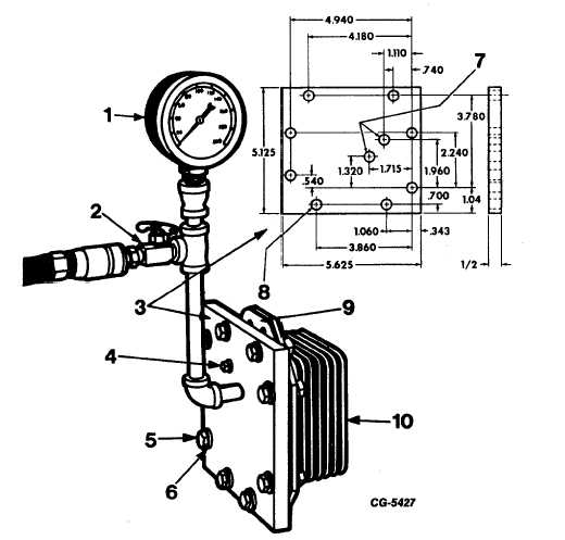
Attach test plate and gasket to core assembly
mounting face flange (Figure 134). The test plate
must be made locally according to the dimensions in
the insert in Figure 134. Obtain engine oil cooler
housing gasket from service parts stock.
NOTE: The oil inlet opening in the cooler core
assembly is located in one of two locations.
Therefore, the test plate must include a tapped
hole for either location to permit applying air
pressure to the core. Install test plate pipe plug
at oil inlet hole not in use.
2.
Install pressure gauge, air control valve and quick
connect air coupler to test plate (Figure 134). Apply
80 to 100 lbs. of air pressurelt6 the core assembly.
3.
Immerse oil cooler core assembly in a container of
water. If a leak is observed, replace core assembly.
CAUTION: Use adequate safety precautions when
preforming pressure test.
Fig. 134 Pressure Testing Engine Oil Cooler Core Assembly
1. Pressure gauge
6. Flat washers - (16 required)
2. Air control valve
7. Drill & tap 1/8 PT THD. this side two holes
3. Test plate (make locally)
8. .375 Dia. - (8 holes)
4. Pipe plug 1/8 NPT
9. Gasket, oil cooler housing IH No. 446647-C1
5. Hex head bolts 5/16 NC x 1% - (8 required)
10. Core assembly, oil cooler
CGES-210 Page 54
PRINTED IN UNITED STATES OF AMERICA
|