|
| |
ENGINE DIVISION SERVICE MANUAL
TM 5-4210-230-14&P-1
ENGINE
5.
Check the pump shaft clearance in the bore. To
correct for wear beyond limits given in specifications,
replace pump assembly.
6.
Check backlash between pump body gears. If this
exceeds the figure shown in the specifications,
replace gears.
7.
Establish body gear end clearance.
NOTE: The oil pump cover gasket controls the
clearance (end play) between the pump body gears
and the pump cover. Add or remove gaskets to
obtain desired clearance. See '"Specifications."
8.
When installing pump gears and shaft, these parts
should be oiled liberally with engine oil for initial
lubrication.
9.
Before installing the relief valve in the pump body,
insure valve is free of burrs and the valve bore is free
of varnish so the valve operates smoothly in its bore.
NOTE: If it becomes necessary to remove burrs from
the valve, insure valve edges are not rounded.
10.
Check relief valve spring for proper tension. See
SPECIFICATIONS.
11.
When assembling the screen assembly to the pump
body make sure the gasket is in place. Then tighten
bolts securely, Figure 132.
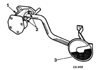
Fig. 132 Oil Pump and Screen Assembly
1. Oil pump
2. Bolts
3. Screen assembly
Oil Cooler and Filter Base
Figure 133 illustrates an exploded view of the oil
cooler and filter base. Upon engine overhaul, the oil cooler
and filter base, if so equipped, should be disassembled and
the cooler element cleaned in a commercial radiator type
solvent. Then flush the element with clean water until rinse
water runs clear.
Fig. 133 Exploded View of Oil Cooler and Filter Base
1. Filter base
5. O-ring
2. Gaskets
6. Plug
3. Valve
7. Cooler element
4. Spring
8. Cooler body
Check the relief valve spring for proper tension, see
SPECIFICATIONS. Also, check the valve for burrs or
scratches. Small burrs or scratches may be removed with
crocus cloth.
When reassembling the oil cooler, use new gaskets
and tighten the bolts securely.
NOTE: On engines not equipped with the oil
cooler, the filter base should be cleaned and
passages checked clear of restrictions.
Oil Cooler Pressure Test
Where conditions indicate the need for testing the
engine oil cooler core assembly for leaks, the core inlet and
outlet openings must be closed off and the assembly
pressurized. Instructions for pressure testing the oil cooler
core assembly are as follows:
CGES-210 Page 53
PRINTED IN UNITED STATES OF AMERICA
|