|
| |
ENGINE DIVISION SERVICE MANUAL
TM 5-4210-230-14&P-1
ENGINE
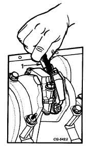
Fig. 129 Checking Connecting Rod End Clearance
1. Feeler gauge
Oil Pump Assembly
The oil pump, Figure 130 consists of two gears and a
pressure relief valve enclosed in the body. The pump is
driven from the distributor drive gear which, in turn, is driven
by a helical gear on the camshaft.
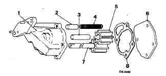
Fig. 130 Exploded View of Oil Pump
1. Body
5. Idler gear
2. Valve
6. Cover
3. Idler shaft
7. Drive shaft and gear
4. Spring
8. Gasket
The body is equipped with a regulator valve that
limits oil pressure to approximately 50 psi.
The pump intake is through a screen assembly
attached to the pump body. A mesh screen filters out
particles of dirt which may be present.
A thorough cleaning and inspection of the oil pump
should be made whenever the oil pan is removed from the
engine. The recommended inspection and repair procedures
are as follows:
1.
Wash all pump parts and screen assembly in
cleaning solvent.
2.
With pump cover removed and gears and shaft in
place, exert pressure against the gears with the
thumb so as to push the gears away from the outlet
side of the pump.
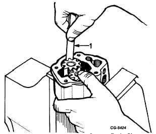
3.
While holding the gears in this manner, measure the
clearance between the outside diameter of the gear
and the bore of the housing, Figure 131. Clearance
should be within the limits given in the specifications.
Fig. 131 Measure Pump Gear-to-Body Clearance
1. Gauge
4.
If clearance is less than specifications, obtain new
parts.
CGES-210 Page 52
PRINTED IN UNITED STATES OF AMERICA
|