|
| |
ENGINE DIVISION SERVICE MANUAL
TM 5-4210-230-14&P-1
ENGINE
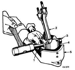
Heat piston in boiling water or piston heater and after
placing piston in vise drive pin from assembly with a suitable
remover or brass drift and soft hammer, Figure 85.
Fig. 85 Removing Piston Pin
1.
Brass drift
4.
Piston
2.
Connecting rod
5.
Piston vise
3.
Pin
After the pin is removed, separate the piston from the
connecting rod, taking precaution to see that the parts are
marked so they may be reinstalled in their respective cylinders
unless defective.
NOTE:
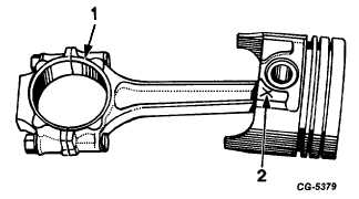
Pistons should also be marked at this time
to insure they are reinstalled in the same
position on the connecting rod as they
were removed, Figure 86. Mark the
pistons so that the mark will not be
removed during cleaning operation. If new
pistons are installed, piston may be -
installed either way on the connecting rod.
Fig. 86 Mark Piston for Identical Reinstallation on
Connecting Rod
1.
Large chamfer
2.
Place mark here
Remove all old rings and immerse all parts of the
piston in cleaning solvent and clean thoroughly. Use a special
ring groove cleaner on broken piston ring to clean all carbon
from the piston ring grooves.
NOTE:
Never use a caustic solution for cleaning
aluminum pistons.
Inspect the pistons for scuffed or scored skirts or
cracked or worn ring lands, discarding any showing such
condition.
To select the correct size pistons for an engine
overhaul, the size of the cylinder bore diameters must be
determined first. This can be accomplished with the use of an
inside reading micrometer SE-686 or dial bore gauge SE-
2331. (Refer to Figure 71.) Each bore should be measured at
the top of ring travel and the lower end of ring travel both
parallel and at right angles to the crankshaft.
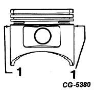
After the cylinder bores have been measured and
recorded, the next step is to select a piston to fit a certain
bore. This is accomplished by measuring the piston at the top
of the skirt across the thrust faces with an outside micrometer,
Figure 87. The size piston selected should be large enough to
permit cleaning up the cylinder bore and provide the proper
running clearance as shown in the specifications.
Cylinder blocks having deep scuff or score marks
may require reboring for use of oversize pistons; therefore, the
foregoing information still applies.
Fig. 87
1.
Measure piston at this area for fitting.
CGES-210 Page 31
PRINTED IN UNITED STATES OF AMERICA
|