|
| |
ENGINE DIVISION SERVICE MANUAL
TM 5-4210-230-14&P-1
ENGINE
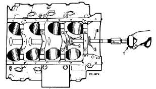
Fig. 81 Installing Second Bearing
1.
Slide hammer
5.
C-washer
2.
Second adapter
6.
Index oil holes
3.
Front adapter
7.
Bearing
4.
Bar
10.
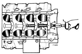
Remove the "C" washer and use the second adapter
as a pilot. Pull the front bearing from the crankcase,
Figure 82.
Fig. 82 Removing Front Bearing
1.
Slide hammer
4.
Bar
2.
Second adapter
5.
Front adaptor
3.
Bearing
6.
C-washer
11.
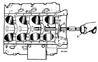
Remove the bar and front adapter and position the
new bearing on the front adapter. Slide the bar into
the block and through the second adapter serving as
a pilot, Figure 83.
Fig. 83 Installing Front Bearing
1.
Slide hammer
5.
Second adapter
2.
Front adapter
6.
Bar
3.
C-washer
7.
Index oil holes
4.
Bearing
12.
Align the oil holes and drive in the front bearing,
Figure 83.
13.
The fourth and rear bearings are installed in a
manner similar to the front and second bearings
using SE1897-7 adapters and working from the rear
of the block.
Pistons and Piston Pins
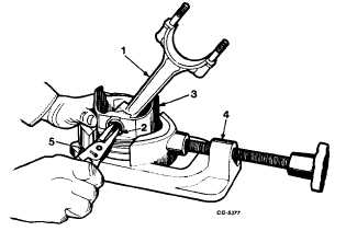
To disassemble the connecting rod from the piston
and piston pin assembly, remove the piston pin retainers from
each end of the pin using Tru-Arc pliers, Figure 84.
Fig. 84 Removing Piston Pin Retainers
1.
Connecting rod
4.
Piston vise
2.
Retainer
5.
Pliers
3.
Piston
CGES-210 Page 30
PRINTED IN UNITED STATES OF AMERICA
|


