|
| |
ENGINE DIVISION SERVICE MANUAL
TM 5-4210-230-14&P-1
ENGINE
inder bore. Never use gasoline, kerosene or commercial
cleaners to clean cylinders. Solvents of this nature will not
remove abrasives from the walls. Rapid engine wear and ring
failure results from failing to properly clean abrasives from the
cylinders.
However, if the wear exceeds the previously mentioned
limits, it is recommended to rebore the cylinder of cylinders to
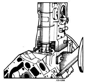
within .003" of the required oversize diameter, Figure 75. This
will allow enough stock for the final step of honing the bores,
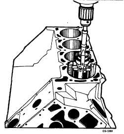
Figure 76, so that the exact clearance may be obtained for the
selected oversize piston. When performing the honing
operation, the hone should be stroked up and down to
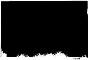
produce a crosshatch pattern on the cylinder wall as shown in
Figure 77. The faster the hone rotates, the faster it must be
stroked up and down to produce the desired crosshatch
pattern.
NOTE: After the honing operation is completed .
the sharp burred edge that develops at the
bottom of a newly honed cylinder should be
removed manually with emery cloth . Then
thoroughly clean the block and cylinder bores.
Fig. 75 Reboring Cylinder Using SE-1399 Boring Machine
Wipe as much of the abrasive deposits from the
cylinder wall as possible. Then swab out each abrasive-
coated cylinder with clean SAE-10 oil and carefully wipe it
with a clean cloth. One swabbing and wiping is not sufficient.
Three complete operations are usually required - more may
be necessary. Continue cleaning until a clean, white rag
shows no evidence of discoloration when wiped through the
cylinder bore. Never use gasoline, kerosene or commercial
cleaners to clean cylinders after honing. Solvents of this
nature will not remove abrasives from the walls. Rapid engine
wear and ring failure result from failing to properly clean
abrasives from the cylinders.
Fig. 76 Honing cylinder bore Using SE-784 Cylinder Grinder
Fig. 77 Proper Honing Leaves a Crosshatch on the Cylinder
Wall
Inspect the camshaft bearings for wear and proper
running clearance. See "Specifications." If the limits are
exceeded, replace the bearings. This can be accomplished
with the special camshaft bearing remover and installer SE-
1897 with two SE-1897-7 adapters and the slide hammer and
adapter from puller set SE-1879.
NOTE: Oil holes must be in alignment with holes
in the crankcase.
1.
Position one adapter SE-1897-7 in the second bearing
with the flange to -ward the rear of the block, Fig. 78.
CGES-210 Page 28
PRINTED IN UNITED STATES OF AMERICA
|


