|
| |
ENGINE DIVISION SERVICE MANUAL
TM 5-4210-230-14&P-1
ENGINE
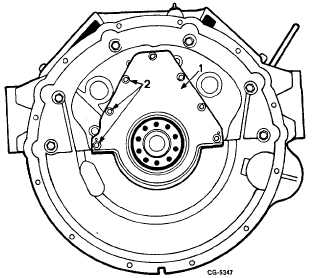
Fig. 54 Rear Oil Seal Retainer Plate Removal
1. Retainer plate
2. Bolts
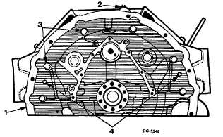
Fig. 55 Flywheel Housing Removal
1. Flywheel housing
2. Oil pressure sending unit
3. Mounting bolts
4. Dowel pins
61.
Remove oil pressure sending unit from rear of engine,
Figure 55.
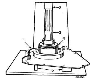
62.
Press rear oil seal from retainer plate using handle
from SE-1905 and 4-1/8" disc, Figure 56.
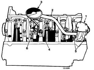
63.
Remove oil pump and pick up tube mounting bolts and
nut, Figure 57. Lift oil pump and withdraw pump drive
shaft from cylinder block.
Fig. 56 Rear Oil Seal Removal
1. Retainer plate
3. Handle
2. Press ram
4. Disc
Fig. 57 Oil Pump Removal
1. Pump
4. Mounting nut
2. Tube
5. Mounting bolts
3. Screen
6. Bracket
64.
Remove oil level gauge tube.
65.
Rotate the crankshaft to position the journals for
removal of the connecting rod assemblies, Figure 58.
NOTE: Before removing the piston assemblies,
always remove the ridge from the top of the
cylinder bore.
CGES-210 Page 22
PRINTED IN UNITED STATES OF AMERICA
|