|
| |
ENGINE DIVISION SERVICE MANUAL
TM 5-4210-230-14&P-1
ENGINE
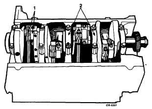
Fig. 58 Positioning Connecting Rods for Removal
1. Connecting rod caps
2. Main bearing caps
66.
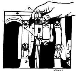
Remove the cap and push the connecting rod and
piston assemblies from the cylinder bore, Figures 59
and 60. Replace the cap and the bearing inserts on the
rod so the numbered sides match. The connecting rod
and piston assemblies are numbered so they can be
reinstalled in their respective cylinders.
Fig. 59 Connecting Rod Cap Removal
1. Cap and rod identification
2. Cap
3. Connecting rod
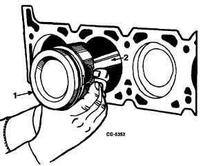
Fig. 60 Connecting Rod and Piston Removal
1. Piston
2. Connecting Rod
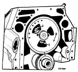
67.
Remove the two bolts and lockwashers securing the
camshaft thrust flange to the crankcase, Figure 61.
Fig. 61 Thrust Flange Bolt Removal
1. Thrust flange bolts
2. Camshaft gear
CGES-210 Page 23
PRINTED IN UNITED STATES OF AMERICA
|