|
| |
ENGINE DIVISION SERVICE MANUAL
TM 5-4210-230-14&P-1
ENGINE
38.
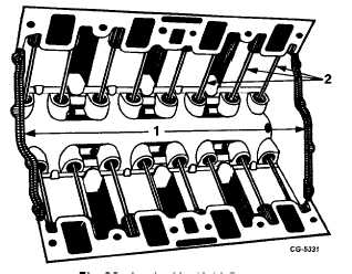
Remove intake manifold seals, Figure 38.
Fig. 38 Intake Manifold Seals
1. Intake manifold seals
2. Push rods
39.
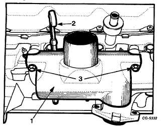
Remove manifold heat shroud from right exhaust
manifold, Figure 39.
40.
Remove oil level gauge from tube, Figure 39.
Fig. 39 Head Shroud Removal
1. Heat shroud
2. Mounting bolts
3. Oil level gauge
41.
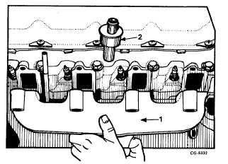
Remove right exhaust manifold and gasket by
removing remaining six manifold bolts, Figure 40.
Remove air manifold check valve.
Fig. 40 Removing Right Exhaust Manifold
1. Exhaust manifold
2. Air manifold check valve
42.
Repeat Step 41 and remove manifold and gasket from
opposite cylinder head and opposite air manifold check
valve.
43.
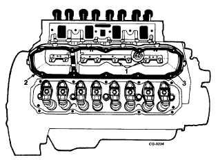
Remove cylinder head cover bolts on both banks and
remove covers and gaskets from both heads, Figure
41.
NOTE: The cylinder head covers use oil deflector
baffles to direct the path of the oil from the push
rods.
Fig. 41 Removing Cylinder Head Covers
1. Oil deflector baffles
2. Cylinder head cover
3. Gasket
44.
Remove flange head bolts securing rocker arms to
cylinder heads, Figure 42. Remove rocker arms and
pivots from cylinder heads.
CGES-210 Page 18
PRINTED IN UNITED STATES OF AMERICA
|