|
| |
ENGINE DIVISION SERVICE MANUAL
TM 5-4210-230-14&P-1
ENGINE
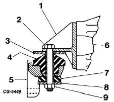
Fig. 7 Engine Rear Mounting with Two-Piece Insulator
1.
Bracket
2.
Bolt-torque to 160-175 ft. lbs.
3.
Washer
4.
Upper insulator
5.
Bracket to frame rail
6.
Flywheel housing
7.
Lower insulator
8.
Washer
9.
Locknut
CRANKCASE VENTILATION SYSTEM
The purpose of this system is to prevent crankcase
vapors from entering the atmosphere by drawing the vapors
into the intake manifold and burning them with the normal fuel
mixture. The system utilizes the vacuum created in the intake
manifold to draw clean air through the crankcase and valve
chamber. Fresh air enters the cylinder head cover through
the flame arrestor by route of the connecting hose from the air
cleaner. The flame arrestor must be serviced at intervals
according to the "Operator's Manual."
The crankcase ventilator valve, Figure 8 located in
the right cylinder head cover varies the air flow through the
crankcase to meet changing conditions at all engine speeds
and loads. The system will work effectively as long as all
component parts are clean and free from sludge and foreign
material.
The valve should be serviced and the system
inspected and cleaned at intervals set forth in the "Operator's
Manual." It may be necessary to inspect and clean the system
more frequently under adverse driving or weather conditions.
To check the operation of the system, first remove
the valve from the cylinder head cover; then with the engine
operating, a vacuum should be felt at the end of the valve. If
no vacuum is present, the valve, hose and fitting should be
removed and cause of the restriction determined. The inner
chamber of the valve should be checked by inserting a stiff
wire into the valve body to see that it can be moved freely.
Upon reinstallation, the crankcase ventilation valve should be
installed as indicated on the valve by an arrow.
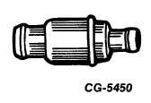
Fig. 8 Crankcase Ventilator Valve of One-Piece Construction
The oil filter cap is non-vented, and therefore,
requires no service.
ENGINE REMOVAL
Engine removal procedures will vary between vehicle
models and also between individual chassis because of
various equipment and accessories. The following outline
covers, in general, the engine disconnect points and lifting
instructions.
Preliminary Instructions
1. Remove front bumper, if equipped with steel hood.
2. Raise hood.
3. Disconnect battery cable from battery.
4. Drain radiator and engine block. See Figures 2 & 3 for
location of engine coolant drain cocks.
5. Drain oil from engine oil pan.
6. Remove hood assembly.
7. Disconnect shutter cylinder air line, if so equipped.
8. Disconnect radiator hoses.
9. Remove radiator support and core assembly (fiberglass
hood only). If equipped with steel hood, disconnect
headlamp, etc., wiring at cowl and remove radiator
support and core assembly with fenders and splash
panels as an assembly.
CGES-210 Page 8
PRINTED IN UNITED STATES OF AMERICA
|