|
| |
ENGINE DIVISION SERVICE MANUAL
TM 5-4210-230-14&P-1
ENGINE
ENGINE LUBRICATION PRIMING
When assembling the overhauled engine, it is
necessary to thoroughly lubricate the various running parts
with clean engine oil to assure initial lubrication when engine
is first started. However, to further make certain that
complete initial lubrication is available, the engine lubricating
system should be pressure primed or charged with oil. The oil
leak detector, SE-1632, can be used for this purpose. Attach
the line from the oil leak detector to a suitable fitting such as
the main oil gallery plug located on the left side of the
crankcase. Inject sufficient oil into the engine to fill the oil
filter and charge the entire system. Use only clean engine oil
of the grade to be used for engine break-in. New or
overhauled engines that have been in storage over an
extended period should also be primed in a similar manner.
In addition to priming engines that have been stored, the
engines should be turned over a few times while being
primed.
NOTE: Disconnect the coil primary wire
when performing this operation to prevent
the engine from starting.
When the priming procedure is used, make certain
the oil level is checked before the engine is put into service.
Caution should be taken so as not to overfill or have
insufficient oil as a result of using the pressure priming
procedure.
Priming the engine will minimize the possibility of
scuffing or heat buildup in the areas of friction, which could
lead to immediate or eventual failures.
OIL FILTER (Spin-On Type)
Replace the oil filter by using the following
procedure:
1.
Remove
oil
filter
assembly
by
turning
counterclockwise with the hands or a suitable tool.
Clean the filter mounting pad.
2.
Coat the gasket on the new filter with a film of
grease.
3.
Place the new filter in position on the center tube.
Hand tighten 1/2 to 3/4 turn after the gasket first
contacts the base of the mounting pad.
4.
Start engine and run for at least five minutes to warm
oil and check for leaks. Also check engine oil level.
ENGINE MOUNTINGS
Engine mountings may vary between vehicle models.
The mountings illustrated are both of the two-piece insulator
type.
Front Mountings
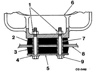
The engine front mounting shown in Figure 6 utilizes
a two-piece insulator with sleeves. When assembling,
position component parts as shown and tighten hex head bolt
to 75 to 85 ft. lbs.
Fig. 6 Engine Front Mounting with Two-Piece Insulator
1.
Tighten to 75 - 85 ft. lbs. torque (threads lubricated)
2.
Insulator- upper
3.
Insulator - lower
4.
Hardened washer
5.
Retainer
6.
Engine mounting bracket
7.
Sleeve
8.
Crossmember
9.
Bolt
Rear Mountings
The engine rear mountings shown in Figure 7 also
utilizes a two-piece insulator. When assembling, position
component parts as shown and tighten nuts to 160 to 175 ft.
lbs.
CGES-210 Page 7
PRINTED IN UNITED STATES OF AMERICA
|

