|
| |
ENGINE DIVISION SERVICE MANUAL
TM 5-4210-230-14&P-1
ENGINE
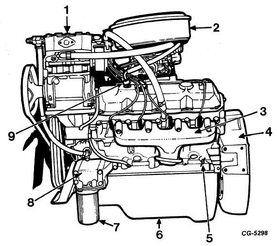
Fig. 2 Left Side View of Engine
1.
Air compressor
6.
Oil pan
2.
Air cleaner
7.
Oil filter
3.
Exhaust manifold
8.
Oil cooler
4.
Flywheel housing
9.
Flame arrestor
5.
Drain cock
The camshaft is supported by five insert-type
bearings pressed into the block and is driven by a drive gear
keyed to the crankshaft. The end thrust of the camshaft is
controlled by a thrust flange located between the front
camshaft journal and the distributor drive gear.
The
aluminum-alloy
pistons
are
fitted
with
compression rings and an oil ring and are used in the engine
with forged steel connecting rods. The full-floating type piston
pins are held in place in the pistons at the ends of the pins by
snap rings. The lower end of the connecting rod and cap
contain locking type bearing inserts. The rods and caps are
numbered for identification and reassembly.
CGES-210 Page 3
PRINTED IN UNITED STATES OF AMERICA
|