|
| |
ENGINE DIVISION SERVICE MANUAL
TM 5-4210-230-14&P-1
ENGINE
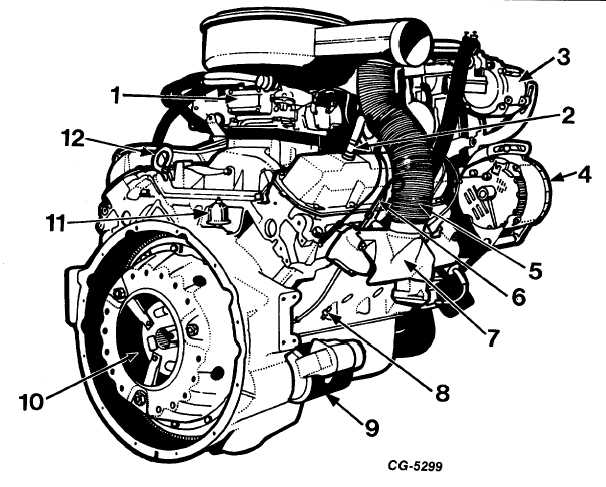
Fig. 3 Right Rear View of Engine
1.
Carburetor
7.
Manifold shroud
2.
PCV valve
8.
Drain cock
3.
Air pump
9.
Starting motor
4.
Alternator
10.
Clutch
5.
Shroud hose
11.
Oil pressure sending unit
6.
Dipstick
12.
Lifting eye
The hydraulic valve lifters minimize engine noise and
maintain zero valve lash or tappet clearance. This eliminates
the need for periodic adjustment.
The cylinder head assemblies feature a high
turbulence-type of combustion chamber which provides
superior combustion characteristics to produce very high
volumetric and thermal efficiencies. The cylinder heads used
on the engines are equipped with a positive valve rotating
mechanism on the exhaust valve only. This device is called a
"Roto Coil" and is located at the base of each exhaust valve
spring. The cylinder heads also incorporate an integral air
manifold.
Another important feature of the cylinder heads is
that they are completely interchangeable from one cylinder
bank to the other bank. The cylinder head gaskets are made
of composition material which prevents compression leakage
between the cylinder block and cylinder head. The gaskets
also prevent leakage of water from the water jackets into the
cylinders. The gaskets are also interchangeable from one
bank to another.
When viewing the engine from the driver's seat, the
cylinders on the left bank are numbered 2, 4, 6 and 8 with No.
2 being at the front. Similarly, the cylinders on the right bank
are numbered
CGES-210 Page 4
PRINTED IN UNITED STATES OF AMERICA
|