|
| |
ENGINE DIVISION SERVICE MANUAL
TM 5-4210-230-14&P-1
ENGINE
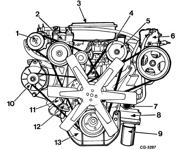
Fig. 1 Front View of Engine
1.
Air pump
8.
Oil Cooler
2.
Freon compressor
9.
Oil filter
3.
Air cleaner
10.
Alternator
4.
Engine water inlet
11.
Gasoline filter
5.
Power steering pump
12.
Fuel pump
6.
Air compressor
13.
Engine mounting bracket
7.
Engine water outlet
ENGINE DESCRIPTION
The V-Series engines covered in this section are 8-
cylinder,
overhead
valve,
900
type.
Dimensional
specifications of the various models are listed under
"Specifications." Figures 1, 2 and 3 illustrate the complete
engine assembly.
The basic unit of the engine, the cylinder block and
upper crankcase, is cast in one piece and is of extremely rigid
construction. It provides full-length water jackets surrounding
each of the cylinders. This unit forms the major section of the
engine as it is fitted with the crankshaft, camshaft, pistons
and various related parts.
The forged alloy steel crankshaft is supported by five
insert-type main bearings. Crankshaft end thrust is controlled
by the flanges of the No. 3 main bearing.
CGES-210 Page 2
PRINTED IN UNITED STATES OF AMERICA
|