|
| |
TRUCK SERVICE MANUAL
TM 5-4210-230-14&P-1
ELECTRICAL
4.
Grasp bulb and pull straight out to remove plug-in
type bulb from socket.
5.
Inspect light assembly and gasket and replace if
damaged.
6.
Push new bulb into socket.
7.
Position socket (with bulb) into light assembly and
turn socket one-eighth turn clock-wise to secure.
8.
Position light assembly (with seal and trim bezel
where used) into mounting recess in cab. Secure
with mounting screws.
9.
Check light operation.
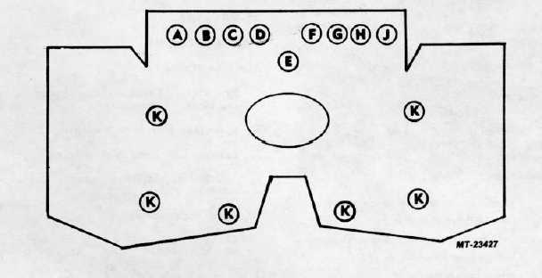
Fig. 11 Instrument Cluster Light Locations (As viewed from front of vehicle)
Legend
A.
Right Turn Indicator
G.
Antilock Warning (Some Models)
B.
Low Air Pressure Warning
H.
Low Oil Pressure/High Water
C.
Antilock Warning (Some Models)
Temperature Warning
D.
Park/Hydr. Brake Warning
J.
Left Turn Indicator
E.
High Beam Indicator
K.
Panel Illumination
F.
Power Divider Lock Warning or
FGR Service Indicator
INSTRUMENT CLUSTER LIGHTS
Locations of instrument cluster illumination, indicator and
warning lights are shown in Figure 11.
BULB REPLACEMENT
Procedures for replacing bulbs in instrument cluster lights are
as follows:
Indicator and Warning Lights: (A thru J, Figure 11).
1.
Remove instrument cluster cover screws (5) and
remove cover to expose warning and indicator lights.
CTS-2781 Page 7
PRINTED IN UNITED STATES OF AMERICA
|